- MAIN CONTENTS
This company standards set rules for the mass flow meter’s product classification, technical requirements, testing
methods, inspection rules and marks, packing, transportation and storage.
The standards are applicable to the mass flow meter measuring liquid in the pipe with pressure.
- NORMATIVE REFERENCES
Some basic rules and terms of the following documents are recommended as the criteria of ZE STANDARDS.
| JJF 1001-1998 | General measurement terms and definitions |
| JJF 1002-2010 | National compile rules for metrological verification regulation |
| JJG 1038-2008 | Coriolis mass flow meters verification regulation |
| GB 4208-2008 | Outer shell Ex-proof rate (IP code) |
| GB 3836.1-2000 | Electrical equipment in explosive gases-part 1: general requirements |
| GB 3836.2-2000 | Electrical equipment in explosive gases-part 2: Ex-proof “D” |
| GB 3836.4-2000 | Electrical equipment in explosive gases-part 4: inner safety “I” |
| GB/T 2423.10-2008 | Electrical and electronic products test-part 2: test method test Fc and guideline |
| GB 14048.1-2006 | Switch and control equipment in low-pressure environment-part 1: general |
| GB/T 191-2008 | Packing, storage and transportation signs. |
| GB/T 13384-2008 | Mechanical and electrical products general packaging technical requirements |
| GB/T 9113.1-2000 | Face and raised flange |
| JB/T 9329-1999(2009) | Instruments transportation, storage environment and basic testing methods |
| GB/T 9969-2008 | Industrial product manual: General |
3 Product Classifications
3.1 Classification
Classification can be made according to the structure:
3.1.1 Integral type
3.1.2 Separate type
3.1.3 Separate types of high-temperature
3.1.4 Ex-proof type
3.1.4.1 Sensor: Integral type ExdibⅡCT4~T6; Separate type ExdibⅡCT3~T6;
3.1.4.2 Transmitter: Exd[ib]ⅡCT6(ⅡC including H2)
The product model is as follows:
ZE — □□□ □ □ □ □ □ □ □ □ Y □□□
—— ——— — — — — — — — — — ———
0 1 2 3 4 5 6 7 8 9 10 11
Model information:
- ZE-mass flow meter:
1.DN(mm):010—10、015—15、020—20、025—25、040—40、050—50、
080—80、100—100、150—150、200—200。
2.Structure: 1—Integral type(-50℃~+125℃) 2—Separate type(-50℃~+200℃)
3—non-explosion type (high-temperature 50℃~+300℃)
3. Sensor: U—U-type W—micro-bend type
- Transmitter: P—general type D—digital type
5. IP: A—general type B—ex-proof type
(integral type: ExdibⅡCT4~T6; separate type: ExdibⅡCT3~T6; transmitter ex-proof type: Exd[ib]ⅡCT6(ⅡC
including H2)
- Power supply: 1-24 VDC 2-220 VAC
- Output Interface: S-RS485 N-no
- Nominal pressure (MPa): 1—1.6 2—2.5 3—4.0 4—6.4
- Output signal: F-pulse signal I-(4 ~ 20) mA
- Medium: Y-liquid
- Accuracy: 010—0.10% 015—0.15% 020—0.20% 050—0.50%
Example: ZE-080 1 U D B 1 S 2 F Y 010
ZE-mass flow meter, DN DN80, integral type, digital circuit, explosion-proof type, power supply 24 VDC, output interface
RS485, PD 2.5 MPa, pulse output l, liquid, accuracy:0.1
3.3 Low flow cutoff
When the flow rate is more than 1%Qmax, the output flow rate should be settled to 0.
3.4 High-density liquid
When the liquid density is beyond the user-settled value, the meter will display zero flow rate or the flow rate value before
the high-density liquid.
3.5 basic parameters
3.5.1 Accuracy : 0.1% 0.15%、0.2%、0.5%;
3.5.2 Power supply::24VDC ±25%;220VAC
、
50Hz±1Hz;
3.5.3 PN: 1.6 MPa, 2.5 MPa, 4.0 MPa, 6.4 MPa;
3.5.4 DN (mm): 10, 15, 20, 25, 40, 50, 80, 100, 150, 200;
3.5.5 Working temperature: 1—Integral type(-50℃~+125℃) 2—Separate type(-50℃~+200℃)
3—separate type with high temperature(-50℃~+300℃)
3.5.6 Density: (0.2 ~ 2.0) g/cm3;
3.5.7 Stability of zero point (see Table 1)
| DN (mm) |
Max flow (t/h) |
Stability of zero point (t/h) |
DN (mm) |
Max flow (t/h) |
Stability of zero point (t/h) |
| 10 | 1.0 | 0.0001 | 50 | 50.0 | 0.0050 |
| 15 | 2.0 | 0.0002 | 80 | 120.0 | 0.012 |
| 20 | 4.0 | 0.0004 | 100 | 200.0 | 0.020 |
| 25 | 6.0 | 0.0006 | 150 | 500.0 | 0.050 |
| 40 | 30.0 | 0.0030 | 200 | 1000.0 | 0.100 |
3.5.8 Flow range
3.5.8.1 Flow range for accuracy of 0.1%、0.15%(Table 2)
| DN(mm) | Displayed flow range(t/h) | Flow range(t/h) |
| 10 | 0.02~1.00 | 0.70~1.00 |
| 15 | 0.04~2.00 | 0.15~2.00 |
| 20 | 0.08~4.00 | 0.7~3.50 |
| 25 | 0.12~6.00 | 1.00~5.50 |
| 40 | 0.60~30.0 | 5.00~327.0 |
| 50 | 1.00~50.0 | 8.00~450.0 |
| 80 | 2.40~120.0 | 19.0~190.0 |
| 100 | 4.00~200.0 | 32.0~1800.0 |
| 150 | 10.0~500.0 | 80.0~440.0 |
| 200 | 20.0~1000.0 | 70.0~1000.0 |
3.5.8.2 Flow range for accuracy of 0.2%、0.5%(Table 3)
| DN(mm) | Displayed flow range(t/h) | Flow range(t/h) |
| 10 | 0.02~1.00 | 0.70~1.00 |
| 15 | 0.04~2.00 | 0.15~2.00 |
| 20 | 0.08~4.00 | 0.7~3.50 |
| 25 | 0.12~6.00 | 1.00~5.50 |
| 40 | 0.60~30.0 | 5.00~327.0 |
| 50 | 1.00~50.0 | 8.00~450.0 |
| 80 | 2.40~120.0 | 19.0~190.0 |
| 100 | 4.00~200.0 | 32.0~1800.0 |
| 150 | 10.0~500.0 | 80.0~440.0 |
| 200 | 20.0~1000.0 | 70.0~1000.0 |
3.5.9 Basic error (See Table 4)
| Accuracy | 0.1 | 0.15 | 0.2 | 0.5 |
| Limit of the basic error(%) | ±0.1 | ±0.15 | ±0.2 | ±0.5 |
3.5.10 Repeatability
Repeatability can’t exceed 50% of the limit of basic error in 3.5.8.
4 Technical Requirements
4.1 Flow Meter Error
The maximum allowable error can not exceed the value in Table 4.
4.2 Repeatability
The repeatability of each flow rate point can’t exceed 50% of the absolute value of the limit of the basic error.
4.3 Zero point Stability
The zero point stability under working conditions should conform to the requirement in Table 1.
4.4 Density Measurement Range (See Table 5)
| Density Range | (0.2~2.0)g/cm3 |
| Basic Error | Accuracy 0.1%,0.2%: ±0.002g/cm3 ;Accuracy 0.5%: ±0.003g/cm3 |
| Repeatability | 0.001g/cm3 |
4.5 Testing pressure grade
The flow meter should bear the testing pressure that is 1.5 times the nominal pressure. During the 5-minute test, there should
be no damage or leakage.
4.6 Leak test
Implement the leak test of the flow meter with the isolation valve for 5 minutes. The test medium is dry air, and the test pressure
is under nominal pressure. There should be no damage or leakage.
4.7 Insulation Resistance
4.7.1 The insulation resistance between the signal input and the meter shell shouldn’t be less than 20MΩ.
4.7.2 The insulation resistance between the power supply and the meter shell shouldn’t be less than 20MΩ.
4.8 Insulation grade
Each terminal of the electronic display should bear the insulation test of AC voltage:
4.8.1 Power Supply: 24VDC
4.8.1.1 500VAC/50Hz between the signal input and the meter shell;
4.8.1.2 500VAC/50Hz between the power supply and the meter shell;
4.8.2 Power supply 220VAC/50Hz;
4.8.2.1 500VAC/50Hz between the signal input and the meter shell;
4.8.2.2 1500VAC/50Hz between the power supply and the meter shell.
4.9 The resistance ability to transportation environment
According to JB/T9329, after transportation and packaging, the flow meter should keep a good performance and keep up to
the requirements of this standard.
4.9.1 High-Temperature Test: +55℃±2℃
4.9.2 Low Temperature Test: -25℃±2℃;
4.9.3 Continuous shock test: Shock acceleration: 10g±1g; times: 1000 ± 10; frequency: 60~100/min.
4.9.4. Free Drop Test: Height: 100mm, times: 4
4.10 Ex-proof Type
Ex-proof performance test should be implemented and complied with ex-proof performance test regulations in
GB3836.1—2000 and GB3836.2—2000, and the manufacturer must be authorized and granted the ex-proof certificate by
ex-proof testing institution.
4.11 Connection and flange: The connection between flow meter and the pipeline should comply with GB/T9113.1.
4.12 Appearance
4.12.1 The displayed digits should be striking and clear.
4.12.2 Accessories
The flow meter should be neat and have a good appearance. There should be no defects like nicks, cracks, corrosion
and peeling.
4.12.2.1 All the characters should be striking and clear;
4.12.2.2 The surface of the visible part of the fluid flow passage should be smooth and without burr.
- Testing Method
5.1 Testing Condition
5.1.1 Testing Environment
5.1.1.1 Temperature: (+15~+35)℃;
5.1.1.2 Relative Humanity:(45~75)%;
5.1.1.3 Atmospheric Pressure:(86~106)kPa。
5.1.2 Testing Power Supply Condition
Voltage deviation: DC24V±5%;AC220V、50Hz±5%.
5.2 Basic error
The basic error test of the accumulative flow is implemented on the standard calibration equipment. The flow meter is
running for 10 minutes at the flow rate of 75%Qmax before calibration. And then zero point adjustment and calibration will be
implemented. The basic error test could be implemented on the flow rate points successively: Qmax, 0.5Qmax, 0.2Qmax, Qmin
and back to Qmax again. We can also test the flow rate point required by the customer.
The test of each flow rate point should be implemented at least three times; the basic error should comply with the
requirement of 4.1.
5.2.1 The relative error should be calculated by formula (1):
Qij-(QS)ij
Eij = —————— ×100% (1)
(QS)ij
Eij— Relative error of indicating the value of i flow rate point and j calibration, %;
Qij— Total mass flow rate of the calibrated flow meter for the i flow rate point and j calibration, kg;
(QS)ij —Total mass flow rate of the standard flow meter for the i flow rate point and j calibration of this flow rate point, kg。
5.2.2 The cumulative mass flow rate is measured by the calibrated flow meter should be calculated by formula (2)
Nij
Qij = —— (2)
K
Nij— The pulse number output from the calibrated flow meter for the i flow rate point and j calibration of this flow rate point;
K —K Coefficient,1/kg。
5.2.3 The cumulative mass flow rate measured by the calibration rig should be calculated according to formula(3):
ρa ρa
(QS)ij =(MI)ij ×[(1- — )/(1- —)] (3)
ρm ρ
ρ —Fluid density for calibration, kg/m3;
ρm—The standard weight density for calibration, kg/m3;
ρa—Air density, kg/m3;
(MI)ij —The indicating mass value of the weighing Apparatus,kg(or t)。
5.2.4 The relative error of the i-calibrated flow rate point is calculated according to formula (4):

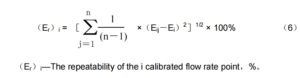
Ei—The relative error of the i calibrated flow rate point,%;
n —Calibration times.
5.2.5 The relative error E is calculated according to formula(5):
![]()
5.3 Repeatability
Repeatability Test can be implemented together with the relative indicating error test at the same time, the test on each
flow rate point should be at least 3 times. The repeatability error should comply with the requirement of 4.2.
5.3.1 The repeatability of the calibrated flow rate point is calculated according to formula (6)
5.3.2 The repeatability is calculated by the formula (7)
Er =[(Er)i]max (7)
Sometimes the flow meter coefficients need to be reset after the calibration. After the coefficients reset, redo the
calibration at flow rate point Qmax、Qmin.
5.4 Zero Point Stability Test
Zero Point Stability Test and the basic error can be implemented at the same time. The test result should comply with
the requirement 4.3.
5.5 Density Calibration
The calibration should be implemented according to JJG 897-1995(Appendix 2). The density should comply with the
requirement of 4.4.
5.6 Pressure Test
The pressure test should be implemented on the flow meter’s outer housing. The flow meter should bear a testing
pressure which is 1.5 times the nominal pressure. During the 5-minute test, there should be no damage or leakage.
5.7 Leak Test
Implement the leak test of the flow meter with an isolation valve for 5min, the medium for the test is air, and the test pressure is
nominal pressure, no damage or leakage occurred.
5.8 Insulation Resistance
The test of the insulation resistance of the electronic display part is implemented by the megohmmeter with rated DC
voltage 500V under the ambient temperature (+15~+35)℃ and relative humidity (45~75)%.
While doing the test, cut off the power supply, place the switch of the electronic display to the “Connected” side, and
then short-circuit the two input terminals and two electronic terminals respectively.
The insulation resistance between the signal input and the device housings should comply with the requirement of 4.7.
The insulation resistance between the signal input and the power supply should comply with the requirement of 4.7.
5.9 Insulation Strength
5.9.1The electronic display part adopts 24VDC power supply. The condition of an insulation strength test:
Ambient Temperature is(15~35)℃,Relative humidity is (45~75)%, the voltage is 500VAC,the current is 1mA
The insulation strength test is implemented to the following part successively:
5.9.1.1 Test between the signal input and the flow meter housing.
Note: One of the two -signal input terminals is grounded and not tested.
5.9.1.2 Test between the power supply and the flow meter housing.
While testing, first the open-circuit voltage of the testing device should be set as 50% of the stipulated voltage, and
then connect the device to it. The power of the testing device should be enough to ensure the voltage drop is less than 10%
after the electronic display part is connected. Increase the voltage steadily from zero to the stipulated value, and then
maintain the value for 1 min, during which no sparkover or flashover occurs. Then decrease the voltage steadily to zero,
and then cut off the power supply.
5.9.2 The display unit of the transmitter should be tested by the same factors of the 220VAC power supply’s insulating strength test:
5.9.2.1 Ambient temperature is (15~35)℃, relative humidity is (45~75)%, and testing voltage is sinusoidal AC voltage
(voltage is 500V, current is 1mA). Conduct an insulating strength test between the meter housing and signal input port (Not the
one which is earthing).
5.9.2.2 Ambient temperature is (15~35)℃, relative humidity is (45~75)%, and testing voltage is sinusoidal AC voltage
(voltage is 1500V, current is 1mA). Conduct an insulating strength test between the meter housing and the power supply port.
First, set the no-load voltage value of the test equipment at 50% of the rated voltage, and connect it to the tested flow meter.
The power of test equipment is sufficient to keep the set voltage from descending more than 10% after the transmitter is
connected. Increase voltage value gradually and smoothly from zero to the rated value. Keep it for 1 minute, and no sparkover
or flashover occurs. Then decrease the voltage value gradually to zero and cut off power.
5.10 The resistance ability to transportation environment
The method and sequence should be according to JB/T 9329.
5.11 Ex-proof Test
The Ex-proof test should be done according to GB3836.1 and GB3836.2. And the Ex-proof certificate must by be
authorized by the national ex-proof institute.
5.12 Appearance
Check the flow meter visually to see if it can meet the requirement of 4.12.
- Rules for inspection
6.1 Ex-factory inspection
6.1.1 Each flow meter must be inspected by the Quality Control department before delivery and should be attached to
product quality certificate.
6.1.2 Inspection steps:
6.1.2.1 Appearance
6.1.2.2 Pressure test
6.1.2.3 Basic error test
6.1.2.4 Repeatability test
6.1.2.5 Leak test
6.1.2.6 Insulation Resistance and Insulation Ratio Test
6.2 Form inspection
6.2.1 When the flow meter is in any of the following conditions, form inspection should be taken to comply with this regulation
standard.
6.2.1.1 New product appraisal test;
6.2.1.2 Great change in design, crafts, and materials;
6.2.1.3 Every three years’ inspection for each product;
6.2.1.4 When there is a great difference between ex-factory inspection and last form inspection;
6.2.1.5 Requested by National Quality Supervision Organization;
6.2.2 Two form inspection samples should be selected at random from the qualified products, the inspection process should
comply with requirements 4.1~4.10.
6.2.3 Judgment rules
In form inspection, if the products don’t comply with items of 4.1, 4.2, 4.5, 4.6, 4.7, 4.8, and then they are unqualified. If the
products don’t comply with other item, then it is allowed to double the inspection samples. If the products still don’t comply
with the rules, then the products are unqualified.
- Marking, package, transportation and storage
7.1 Marking
7.1.1 Flow meters should be marked with a permanent flow direction arrow.
7.1.2 Flow meters should be attached with a nameplate stating the following contents:
7.1.2.1 Manufacturer, trademark, manufacturing date and factory no
7.1.2.2 Product name and model;
7.1.2.3 Accuracy, flow coefficient;
7.1.2.4 Flow range, medium;
7.1.2.5 Nominal diameter, nominal pressure, working temperature, power supply;
7.1.2.6 Material of sensor;
7.1.2.7 Factory license and factory no
7.1.2.8 IP code
7.1.2.9 Anti-Explosion grade, no. and inspection association mark.
7.1.3 Package of flow meter includes following marks:
7.1.3.1 Manufacturer name and address;
7.1.3.2 Product name and model;
7.1.3.3 Factory license and factory no;
7.1.3.4 Flow range and accuracy;
7.1.3.5 Nominal diameter and nominal pressure;
7.1.3.6 And factory no and manufacturing date;
7.1.3.7 Marks like “Handle with Care” and” Keep dry” should comply with GB/T 191.
7.2 Package
7.2.1 The package of the flow meter should comply with GB/T 13384.
7.2.2 The following documents should be put into a packing box:
7.2.2.1 Packing list;
7.2.2.2 Product quality certificate;
7.2.2.3 Product installation and instruction manual. The manual should comply with GB/T 9969.
7.3 Transportation
7.3.1 Handling with care in loading and unloading. Throwing is forbidden.
7.3.2 Flow meters shouldn’t mix with corrosive objects or gas in transportation.
7.3.3 Avoid sunlight and rain during transportation.
7.4 Storage
7.4.1 Flow meters should be stored in a dry and clean warehouse;
7.4.2 Flow meter should be kept indoors where temperature is (-10~+55)℃, and relative humidity is less than 75%, and
without any corrosive gas.