In the industrial field, electromagnetic flowmeters are widely used, such as flow measurement of circulating water pipelines, fresh water pipelines, and salty sewage pipelines in refinery process units; flow measurement of medium pipelines such as concentrated sulfuric acid, dilute sulfuric acid, and intermediate acids in alkylation units.
Flow measurement of pipelines such as alkali liquid and quenched water in sulfur plants. Due to the particularity of the electromagnetic flowmeter measurement principle, its grounding problem directly affects the normal operation and measurement accuracy of the instrument.
Therefore, it is helpful to correctly understand the reasons for the grounding of the electromagnetic flowmeter and to be familiar with the grounding scheme of the electromagnetic flowmeter in different usage situations. For the reasonable selection, installation and commissioning, and troubleshooting of electromagnetic flowmeters.

1. Working principle
Electromagnetic flowmeter is a flow detection instrument based on the working principle of the law of electromagnetic induction. According to Faraday’s law of electromagnetic induction, when a conductor moves in a magnetic field, it generates an induced electric potential by cutting the magnetic lines of force.
The sensor of the electromagnetic flowmeter obtains the potential signal through the positive and negative electrodes located at both ends of the conductor, and then transmits it to the converter through the signal line. After signal amplification and conversion, it is transmitted to the control room.
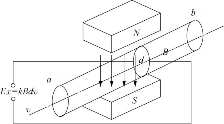
The typical working principle of an electromagnetic flowmeter is shown in Figure 1, where Ex represents the induced electromotive force, k is the coefficient, B represents the magnetic induction intensity, d represents the distance between the two electrodes (the inner diameter of the measuring tube), and v represents the medium flow rate.
2. Grounding problem
The root cause of grounding problems
As can be seen from Figure 1, the induced electromotive force Ex is generated by the magnetic field lines cut by the conductor (measured medium) flowing between the front and rear flanges of the electromagnetic flowmeter (end a to end b). Therefore, the reference potential of the negative end of Ex must be equal to the flow meter The measured medium potential between the two flanges is consistent. In order to strictly ensure the consistency between the two flanges, in addition to ensuring that the flowmeter electrode is in contact with the medium, the zero potential should also be maintained through reliable grounding.
At the same time, due to the small Ex value, the full The range is only 2.5~8.0mV. When the flow rate is very small, it is only a few microvolts. Therefore, in order to avoid the Ex value drift caused by external interference (mainly electrostatic interference), the weak electromotive force Ex measured by the sensor electrode needs to be grounded to complete and Passed losslessly to the converter. The above are two key points for the normal operation of electromagnetic flowmeters, and they are also the fundamental reason why electromagnetic flowmeters are different from other flowmeters in terms of grounding requirements.
Difference from thermocouple signal
When the electromagnetic flowmeter is working, the signal generated between the electrodes is at millivolt level. As mentioned above, this is one of the reasons why its field instruments need to be reliably grounded. However, not all millivolt level signal instruments need to be grounded when working.
In order to better understand the necessity of grounding the electromagnetic flowmeter and avoid falling into cognitive misunderstandings, it can be compared to a thermocouple, which also has a millivolt signal. There is no need to take separate grounding measures when the field instrument is working.
The reason is that the millivolt-level signal of the thermocouple is generated at the hot end and the cold end. Due to the thermoelectric effect, the electrodes of two different materials form positive and negative electrodes at the hot end, and extend to the cold end and negative electrode through the compensation wire. It does not need to be at the same potential as the medium being measured.
The working electrode of the electromagnetic flowmeter is in contact with the medium and maintains the same negative potential, which is a prerequisite for its operation.

3. Grounding scheme
As shown in Figure 1, when the fluid cuts the magnetic field lines to generate a flow signal, a positive potential is generated on one electrode and a negative potential is generated on the other electrode. In order to avoid polarization reactions, the two alternately change.
Since the potential difference is based on the fluid itself as zero potential, the ground point of the output signal of the electromagnetic flowmeter sensor should be electrically connected to the measured medium.
This is a necessary condition for the operation of the electromagnetic flowmeter. If this condition is not met, the electromagnetic flowmeter will not work properly. . Therefore, the midpoint of the input end of the electromagnetic flowmeter converter must be at zero potential and connected to the fluid, so that a symmetrical input loop can be formed.
However, during project implementation, different grounding solutions still need to be adopted for different working conditions.
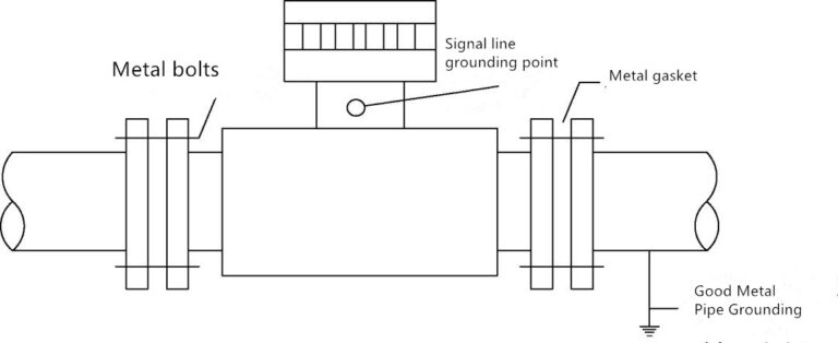
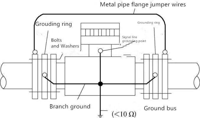
Grounding solutions installed in metal pipes
The medium measured by the electromagnetic flowmeter must be conductive, so when the electromagnetic flowmeter is installed in an unlined metal pipe, if it is confirmed that the metal pipe has been reliably grounded, the electromagnetic flowmeter no longer needs to be grounded separately.
The reason is that the electromagnetic flowmeter has formed a whole through metal gaskets, bolts and pipes, and the potential is 0. Two details should be noted here: In order to avoid magnetic conduction, the electromagnetic flowmeter body is generally made of stainless steel or carbon steel with a non-metallic lining. The electromagnetic flowmeter mentioned above that does not require separate grounding is for the electromagnetic flowmeter whose body is made of stainless steel and other non-metallic linings.
For magnetically conductive metal materials; for carbon steel with non-metal lining, if there is no non-metal flange flange, when using metal gaskets, there is no need to separately ground, but for electromagnetic steel with non-metal flange flange Flow meter, if the resistance value of the connecting bolt is greater than 0.03 Ω (Note: The data comes from GB/T20801.4-2006 “Pressure Pipe Specification Industrial Pipeline Part 4: Production and Installation” Article 10.12.1, the empirical value is less than 5), the same grounding scheme as for non-metallic pipes should be adopted. The grounding scheme of metal pipe electromagnetic flowmeter is shown in Figure 2.
Grounding solutions installed in non-metallic pipes
When the electromagnetic flowmeter is installed on a non-metallic pipe, such as a plastic pipe or a metal pipe with insulating coating or insulating lining, the medium in the pipe cannot be connected to the earth through the metal pipe. Under this working condition, both ends of the sensor should be equipped with grounding rings so that the measured medium flowing in the pipe is well grounded and has zero potential, otherwise the electromagnetic flowmeter will not work properly. The grounding scheme of electromagnetic flowmeter for non-metallic pipelines is shown in Figure 3.
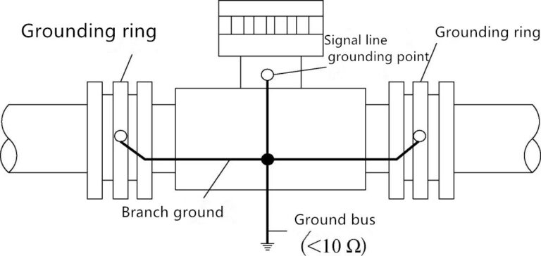
As analyzed in “Grounding Scheme Installed in Metal Pipes”, when the electromagnetic flowmeter is installed on a metal pipeline with a non-metal lining, the grounding scheme is the same as that installed on a non-metallic pipeline, and should also be used as shown in Figure 3 Grounding scheme.
Since the grounding ring does not change the form of the electromagnetic flowmeter and is in direct contact with the medium during operation, it is the preferred solution in most cases, but it is not the only choice in engineering design. Especially for grounding rings made of special materials or grounding rings with larger diameters, in view of their high cost, in such working conditions, the solution of adding grounding electrodes, or “three electrodes”, can be considered to achieve working grounding.
Grounding scheme installed in cathodically protected pipelines
For metal pipelines laid underground and with long distances, in order to prevent electrochemical corrosion, cathodic protection is required or recommended depending on the type of medium. Regardless of whether it is a sacrificial anode cathodic protection scheme or a forced current scheme, metal pipelines have a negative potential to the earth after implementing cathodic protection measures.
For the electromagnetic flowmeter installed on the pipeline under this working condition, the field instrument needs to be grounded as an independent whole and cannot have any conductive circuit connection with the metal pipeline to prevent the cathodic protection current from flowing directly into the earth through the instrument and causing serious damage. The effect of cathodic protection.
At the same time, in order to maintain the integrity of the cathodic protection of metal pipelines, it is also necessary to add wires across the flanges on the pipelines. The grounding scheme of electromagnetic flowmeter in pipeline with cathodic protection is shown in Figure 4. In Figure 4, the grounding ring is insulated from the cathodically protected metal pipe, and good insulation measures must be taken between the bolts and gaskets and the metal pipe.
4. Anti-interference measures
The correct grounding of the electromagnetic flowmeter field instrument is only one of the necessary conditions for its normal operation.
From the perspective of interference sources, external magnetic fields and electric fields will cause interference to the electromagnetic flowmeter.
People do not have good active protection measures for external magnetic field interference. Generally, during the design process, signal lines are required to be twisted and shielded. Cables that reduce magnetic field interference through inductive balancing.
At the same time, when selecting the installation location of the electromagnetic flowmeter, it should be kept away from all sources of electromagnetic interference (such as high-power motors, transformers, etc.). For split-type electromagnetic flowmeters, the signal lines and excitation lines between the converter and the sensor should use the manufacturer’s special cables and be laid in separate pipes.
For electric field interference, in addition to the working grounding of field instruments, the shielding grounding of the cable from the converter to the control room should also be improved in accordance with the specifications. The electromagnetic flowmeter electrical signal loop connection and grounding are shown in Figure 5.

The correct grounding of the electromagnetic flowmeter is crucial to the normal use and long-term operation of the electromagnetic flowmeter. However, during project implementation, it should be understood that “correct grounding” does not mean that a separate grounding must be set, such as the above mentioned When metal pipelines have good grounding measures, separate instrument grounding is no longer needed.
In addition, this article focuses on the pipeline electromagnetic flowmeter. For the insertion electromagnetic flowmeter, the two pipeline flanges can be regarded as a whole, corresponding to the single connecting flange of the insertion electromagnetic flowmeter. For reference, use the above mentioned grounding scheme.