1. Overview
1. Under specific flow conditions, part of the fluid kinetic energy is converted into fluid vibration, and its vibration frequency has a certain proportional relationship with the flow rate (flow rate). A flow meter that works based on this principle is called a fluid vibration flow meter. There are currently three types of fluid vibration flowmeters: vortex flowmeters, precession (vortex precession) flowmeters and jet flowmeters. Fluid vibration flowmeter has the following characteristics:
1) The output is pulse frequency, and its frequency is proportional to the actual volume flow of the fluid being measured. It is not affected by fluid composition, density, pressure, and temperature;
2) The measurement range is wide, and the general range ratio can reach more than 10:1;
3) The accuracy is above average;
4) No moving parts, high reliability;
5) Simple and solid structure, easy installation and low maintenance cost;
6) Wide range of applications, applicable to liquids, gases and vapors.
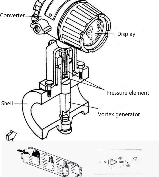
1.2 Working principle
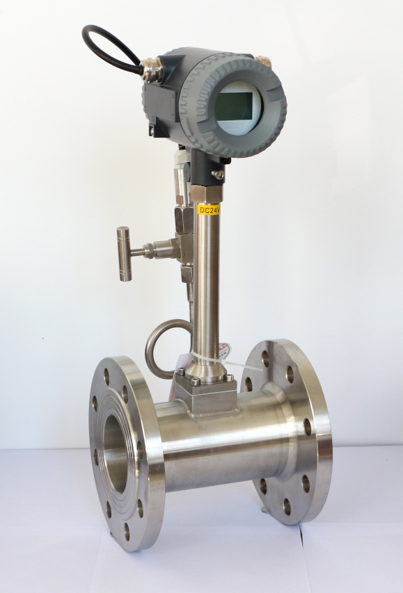
A vortex generating body (bluff body) is set up in the fluid, and regular vortices are alternately generated from both sides of the vortex generating body. This vortex is called a Karman vortex street, and the vortex rows are arranged asymmetrically downstream of the vortex-generating body. The flow rate is proportional to the frequency of vortex occurrence. Suppose the frequency of vortex occurrence is f, then the flow rate Q=K*f, and K is the flow coefficient.
2. Main technical indicators
Technical standard
2.1 Measurement accuracy
Basic error: ±1%
Repeatability error: ±2
2.2 Output signal
Sensor: square wave high level ≥5V, low voltage <1V; current pulse +24VDC
Transmitter: 4~20mA standard signal proportional to the vortex flowmeter
2.3 Medium temperature: -196℃ ~450℃
2.4 Power supply voltage: +13VDC, +24VDC (sensor) +24VDC (transmitter)
2.5 Vortex generators can be divided into two categories: single vortex generators and multiple vortex generators. Single vortex generators are the most commonly used structure. They are composed of circles, rectangles, triangles, etc., and they can also be composed of composite types from these basic types. The multi-vortex generator is combined with the single-vortex generator, which has a certain effect on improving the strength and stability of the vortex street and reducing the lower limit Reynolds number.
2. Vortex detector, there are 5 ways to detect vortex.
a. Use the detection element installed in the vortex generator to directly detect the differential pressure on both sides of the generator.
b. Open a pressure guide hole on the vortex generator, and install a detection element in the pressure guide hole to detect the differential pressure on both sides of the generator.
c. Detect the alternating environment around the vortex generator.
d. Detect the alternating differential pressure on the back of the vortex generator.
e. Detect the vortex array in the wake.
At present, thermal, stress, strain, capacitance, electromagnetic, ultrasonic, photoelectric, and fiber optic
and other detection technologies. According to 5 detection methods,
3. Inspection and debugging
Verification and verification
1. The calibration of the vortex flowmeter needs to be sent to the manufacturer or a unit with calibration qualifications for calibration.
2. The vortex flowmeter can be calibrated on-site using a portable ultrasonic flowmeter.
3. The error of the calibration device should not exceed 1/2 of the basic error limit of the flow meter being tested, and each measurement time should not be less than the shortest measurement time allowed by the device.
4. Use and maintenance
Maintenance and operation
1. Inspection before power on and flow after on-site installation
1) There should be no leakage in the flanges, valves, pressure measuring holes, temperature measuring holes and joints on the main pipe and bypass pipe;
2) Whether the vibration condition of the pipeline complies with the instructions;
3) Is the sensor installed correctly and are the electrical connections of all parts in good condition?
2. Turn on the power for static debugging
When the power is on and the flow is off, the converter should have no output, the instantaneous flow indication is zero, and the cumulative flow has no change. Otherwise, first check whether interference signals are introduced due to poor signal line shielding or grounding, or strong pipe vibration. If it is confirmed that the reason is not the above, you can adjust the potentiometer in the converter, reduce the gain of the amplifier or increase the trigger level of the shaping circuit until the output is zero.
3. Through-flow dynamic debugging
Close the bypass valve and open the upstream and downstream valves. After the flow is stable, the converter outputs continuous pulses with uniform pulse width. The flow indication is stable without jumping. Adjust the valve opening and the output changes accordingly. Otherwise, the potentiometer should be carefully checked and adjusted until the instrument output has neither false triggering nor missing pulses.
5. Troubleshooting
Common faults and solutions:
① There is fluid flowing in the pipeline, but there is no signal output
a. Check whether the instrument wiring is correct and whether there are any short wires
b. Check whether the installation direction of the instrument is correct
c. Check whether the flow rate is lower than the normal flow range
d. Check the power supply voltage.
e. Check whether the measuring probe has frequency output
f. Check whether the measurement circuit board is faulty or whether the settings are correct.
②No fluid flow, but there is signal output
a. Check the grounding of the instrument to see if poor grounding is causing interference.
b. Check whether there is strong mechanical vibration in the pipeline
c. Check whether there is strong electromagnetic interference in the environment, such as high-power electrical appliances or frequency converters and other strong electrical equipment.
d. Check whether the sensitivity is too high.
e. Check whether the measuring probe is faulty.
③The flow rate of the fluid in the pipeline is stable and meets the flow requirements, but the output changes too much and is unstable
a. It may be caused by poor grounding causing interference.
b. It may be that the pipe vibration is too strong, causing interference
c. Check whether the measuring probe is faulty
④The displayed flow rate does not match the actual flow rate and is unstable.
a. It may be that the instrument parameter settings are incorrect.
b. It may be that the measurement error of the temperature and pressure instrument is too large
c. The flow rate may be lower or higher than the normal flow range.
d. It may be that the installation does not meet the requirements, such as uneven installation, obstacles in the pipeline, insufficient straight pipe sections, etc.
6. Installation precautions
Vortex flowmeters are flowmeters that are sensitive to pipeline flow velocity distribution distortion, rotational flow and flow pulsation. Therefore, full attention should be paid to the on-site pipeline installation conditions and the requirements of the manufacturer’s instruction manual should be followed.
Vortex flow meters can be installed indoors or outdoors. If installed in an underground well, there is a possibility of flooding, so a salivary water sensor should be used. The sensor can be installed horizontally, vertically or tilted on the pipeline, but to prevent interference from bubbles and droplets when measuring liquids and gases, attention should be paid to the installation position, as shown in Figure 6-2. Installation of miscible fluids