
When dealing with abrasive slurries, corrosive chemicals, high temperatures, or vacuum conditions, ceramic lining may seem like the ideal solution for an electromagnetic flowmeter.
Ceramics are hard, wear-resistant, and capable of withstanding demanding chemical and thermal environments. However, selecting a ceramic lined electromagnetic flowmeter is not simply a matter of choosing the hardest material or the one with the highest temperature rating.
A ceramic measuring tube may withstand a particular temperature, but the complete flowmeter may have lower operating limits due to its electrodes, seals, mechanical connections, or converter design.
The actual service life of a ceramic lined electromagnetic flowmeter depends on several factors working together:
- Ceramic material composition and manufacturing process
- Abrasion and particle erosion characteristics
- Chemical compatibility with the measured medium
- Operating temperature and thermal shock
- Operating pressure and vacuum conditions
- Electrode, gasket, and sealing materials
- Installation quality and mechanical stress
This guide explains the key engineering considerations when selecting ceramic lined electromagnetic flowmeters for demanding industrial applications.
1. Understanding Ceramic Lining Structures
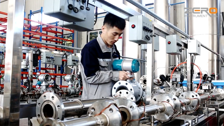
Ceramic lining is not a single, standardized construction. Different manufacturers may use different ceramic materials, manufacturing processes, and mechanical structures.
Two common construction approaches are thermal-sprayed ceramic coatings and integral sintered ceramic measuring tubes.
1.1 Thermal-Sprayed Ceramic Coatings
Thermal spraying applies ceramic material onto a metal substrate to form a protective coating.
The coating can provide excellent surface hardness and wear resistance. However, its performance depends on more than the ceramic material itself.
Important factors include:
- Coating thickness and uniformity
- Porosity and interconnected pores
- Microcracks and unmelted particles
- Bonding strength between the coating and substrate
- Sealing materials and surface treatment
- Corrosion resistance of the underlying metal
A coating may still appear intact while the substrate underneath is already affected by corrosion or coating degradation.
Thermal-sprayed coatings should therefore be evaluated based on their actual manufacturing process and inspection results.
For reference, typical plasma-sprayed coatings may have porosity around 1% to 2%, while some HVOF coatings can achieve porosity below 0.5%. Controlled-atmosphere plasma spraying can produce coatings with very low porosity.
These figures are process-dependent examples, not universal specifications for ceramic lined flowmeters.
1.2 Integral Sintered Ceramic Measuring Tubes
An integral ceramic measuring tube is manufactured by forming and sintering ceramic material into a complete tube.
Compared with a thin ceramic coating, this construction generally has a thicker ceramic wall and a different mechanical connection design.
It can be suitable for many abrasive and corrosive applications, but it is not automatically immune to cracking, thermal shock, or mechanical damage.
The following parameters should be confirmed:
- Ceramic purity and composition
- Sintering additives
- Grain-boundary phases
- Measuring tube diameter and wall thickness
- Mechanical connection structure
- Manufacturer’s allowable operating conditions
Important: Product descriptions such as “ceramic carbide” do not necessarily mean high-purity alumina ceramic. Always request the actual material composition and construction details instead of relying on the general term “ceramic lining.”
2. Selecting Ceramic Lining for Abrasive Applications
Ceramic materials, particularly alumina-based ceramics, offer high hardness and can provide good resistance to particle abrasion.
However, hardness alone does not determine the service life of a flowmeter.
The actual wear rate depends on several interacting factors:
- Particle hardness
- Particle size distribution
- Particle shape and sharpness
- Solid concentration
- Particle impact angle
- Local turbulence and flow velocity
- Operating temperature
- Combined abrasion and chemical corrosion
2.1 Why Flow Velocity Matters
In many erosion models, material loss is represented as a function of flow velocity:
E is proportional to v raised to the power of n.
Here, E represents erosion, v represents velocity, and n is an empirical exponent determined by the material, particles, and flow conditions.
The exponent is not universal.
Particle impact velocity may also differ significantly from the average velocity of the slurry. Therefore, it is not technically correct to assume that doubling the average flow velocity will always increase wear by four to eight times.
2.2 Calculate the Average Flow Velocity
A useful first step in evaluating an abrasive application is to calculate the average velocity inside the measuring tube.
Formula:
v = 4 * Q / (pi * D^2)
Where:
- v = Average flow velocity (m/s)
- Q = Volumetric flow rate (m3/s)
- D = Actual internal diameter of the measuring tube (m)
- pi = 3.1416
Example:
Assume the flow rate is 100 m3/h.
For an actual internal diameter of 100 mm:
v is approximately 3.54 m/s.
If the internal diameter increases to 125 mm:
v is approximately 2.26 m/s.
Reducing velocity may help reduce erosion in many applications. However, increasing the measuring tube diameter is not always the correct solution.
The following conditions must also be checked:
- Minimum operating flow rate
- Measurement accuracy
- Low-flow signal stability
- Risk of solid particle deposition
- Full-pipe operating conditions
A flowmeter should not be oversized simply to reduce wear.
2.3 Particle Characteristics Must Be Evaluated
Coarse particles are not always associated exclusively with impact erosion, and fine particles do not always cause only cutting wear.
The actual wear mechanism depends on particle size, shape, hardness, concentration, and impact angle.
For slurry applications, provide the manufacturer with:
- Particle size distribution
- Particle shape or mineral composition
- Solid concentration and its variation
- Minimum, normal, and maximum flow rates
- Operating temperature and chemical composition
A general description such as “highly abrasive slurry” is not sufficient for reliable material selection.
3. Temperature, Thermal Shock, and Vacuum Conditions
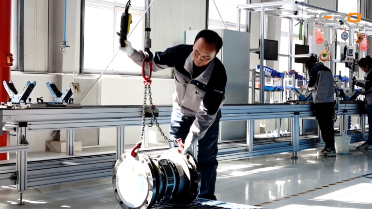
One of the most common mistakes in ceramic flowmeter selection is confusing the temperature resistance of the ceramic material with the allowable process temperature of the complete instrument.
The actual temperature limit may be determined by:
- Electrode connections
- Gaskets and sealing components
- Mechanical joints
- Housing and converter design
- Bonding or clamping structures
- Manufacturer-specific construction limitations
3.1 Check the Actual Model Temperature Rating
Published product specifications demonstrate that temperature limits can vary considerably between models and configurations.
For example:
| Manufacturer / Model | Published configuration information | Temperature reference |
|---|---|---|
| KROHNE OPTIFLUX 5000 | Ceramic measuring tube | Up to approximately +180°C in the referenced configuration |
| ABB ProcessMaster FEP630 | Ceramic carbide configuration | +80°C in the referenced configuration |
| ABB FEP630 | PTFE/PFA configuration | Up to approximately +180°C in the referenced information |
These figures should not be interpreted as universal temperature limits for all ceramic or polymer-lined electromagnetic flowmeters.
Always verify the exact model, nominal diameter, liner construction, and operating conditions against the manufacturer’s current technical documentation.
3.2 Thermal Shock Can Damage Ceramic Structures
Ceramic materials generally offer high compressive strength but are relatively brittle.
Rapid temperature changes can create thermal stresses that may lead to cracking or damage around mechanical connections.
Potentially critical operating conditions include:
- Rapid startup and shutdown
- Repeated heating and cooling cycles
- Steam cleaning
- High-temperature flushing
- Sudden changes in process temperature
Some manufacturers specify allowable temperature differences or maximum temperature change rates.
Do not assume that one universal heating or cooling rate applies to all ceramic flowmeters.
Provide the manufacturer with the actual startup, shutdown, cleaning, and flushing temperature profiles.
3.3 Vacuum Resistance Must Be Verified Separately
Vacuum applications require particular attention.
Polymer liners may be limited by deformation or liner separation under vacuum. Ceramic constructions have different mechanical characteristics, but their vacuum capability still depends on the complete design.
For example, KROHNE OPTIFLUX 5000 documentation identifies its ceramic construction as suitable for full-vacuum conditions.
ABB FEP630 documentation specifies minimum absolute pressure according to liner type, nominal diameter, and temperature.
The important point is that vacuum resistance should never be determined from the material name alone.
Always check the combination of:
- Minimum absolute operating pressure
- Process temperature
- Nominal diameter
- Liner construction
- Mechanical support and connection design
4. Chemical Compatibility: Special Attention to Fluoride Media
Ceramic materials are often considered chemically resistant. However, ceramic is a broad material category, and different compositions can have significantly different chemical resistance.
For alumina ceramics, corrosion behavior depends on:
- Alumina purity
- Glassy phases and grain-boundary composition
- Porosity and density
- Chemical concentration
- Operating temperature
- Exposure duration
Alumina is an amphoteric oxide. Its resistance to strongly acidic and strongly alkaline environments can vary with concentration and temperature.
4.1 Why HF Is a High-Risk Medium
Hydrofluoric acid (HF) and acidic fluoride solutions require particular attention when considering alumina ceramic liners.
Fluoride ions can interact with aluminum and promote dissolution through the formation of aluminum-fluoride complexes.
In polycrystalline alumina, HF may also preferentially attack silicate-containing glassy phases at grain boundaries.
This can lead to:
- Grain-boundary degradation
- Loss of surface integrity
- Particle release
- Progressive material deterioration
Different alumina formulations may show significantly different corrosion behavior.
Therefore, ceramic compatibility should be evaluated using the actual material composition rather than a general alumina resistance chart.
4.2 “Fluoride-Containing Medium” Is Not a Complete Specification
When evaluating fluoride-containing applications, distinguish between:
- Hydrofluoric acid (HF)
- Free fluoride ions
- Total fluoride concentration
- Organic fluorinated compounds
The following information is also necessary:
- pH value
- Chemical concentration
- Operating temperature
- Other acidic or alkaline components
- Cleaning and flushing chemicals
Neutral fluoride salts, acidic fluoride solutions, and hydrofluoric acid should not be assumed to have the same corrosion behavior.
For HF and acidic fluoride applications, alumina and other oxide ceramics containing susceptible grain-boundary phases should be treated as high-risk candidates.
PTFE and PFA are often important alternative materials to evaluate, subject to the actual chemical compatibility and operating conditions.
However, neither PTFE nor PFA should be treated as a universal solution.
Their suitability must also be checked against temperature, vacuum, pressure, permeation, slurry abrasion, electrode materials, and sealing requirements.
5. Comparing Ceramic, PTFE, PFA, and Rubber Linings
Different liner materials serve different industrial applications.
The following table provides a general engineering comparison.
| Selection Factor | Ceramic | PTFE / PFA | Rubber |
|---|---|---|---|
| Abrasion resistance | Generally high in suitable designs | Application-dependent | Depends on rubber formulation |
| Chemical resistance | Depends on ceramic composition | Broad chemical resistance, subject to compatibility | Depends on compound and medium |
| Thermal shock | Requires careful evaluation | Requires evaluation | Requires evaluation |
| Mechanical impact | Brittle; sensitive to impact | More flexible | Generally more elastic |
| Typical applications | Abrasive and selected corrosive media | Chemical and corrosive processes | Water, slurry, and other compatible media |
| Main limitation | Brittleness and thermal stress | Temperature, vacuum, and permeation limits | Chemical and temperature limitations |
The best lining material depends on the dominant failure mechanism.
For example:
- Severe particle abrasion may justify evaluating a ceramic measuring tube.
- Strong chemical corrosion may make PTFE or PFA a more suitable candidate.
- Certain water and slurry applications may be suitable for rubber lining.
- Combined abrasion and corrosion require a complete assessment of both mechanisms.
There is no single liner material that is best for every industrial application.
6. Electrode Materials, Sealing, and Installation
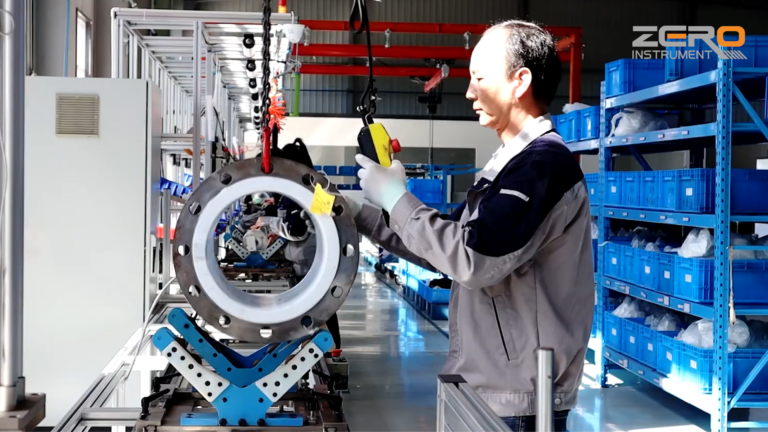
Selecting the correct liner is only part of the process.
The electrodes, grounding structure, gaskets, and mechanical connections must also be compatible with the measured medium.
6.1 Electrode Material Selection
The measuring electrodes of an electromagnetic flowmeter must be electrically conductive.
The term “ceramic electrode” is not sufficiently precise for technical specifications.
Some manufacturers offer specialized wear-resistant electrode solutions, such as cermet (ceramic-metal composite) or platinum electrodes.
For example, KROHNE OPTIFLUX 5000 documentation lists specialized cermet and platinum electrode options.
When selecting electrodes, evaluate:
- Wear resistance
- Chemical compatibility
- Electrical conductivity
- Electrochemical noise
- Electrode replacement requirements
The electrode material must be compatible with both the process chemistry and the measurement principle.
6.2 Check All Wetted Components
A complete wetted-material review should include:
- Measuring electrodes and grounding electrodes or grounding rings.
- Gaskets, O-rings, and other sealing components.
- Coating sealants and auxiliary wetted materials.
- Flanges, mechanical connections, and potential dissimilar-metal contact.
- Normal process media, startup and shutdown fluids, and cleaning chemicals.
A liner that is chemically resistant does not guarantee that every other wetted component will perform reliably.
6.3 Installation Requirements for Ceramic Flowmeters
Ceramic components require careful handling during transportation, installation, and operation.
Important precautions include:
- Avoid impact or direct mechanical force on ceramic components.
- Do not use flange bolts to forcibly pull misaligned pipe connections together.
- Avoid excessive pipe stress and uneven bolt tightening.
- Provide appropriate pipe support.
- Minimize vibration and mechanical shock.
- Consider water hammer and sudden pressure changes.
- Follow the manufacturer’s installation and tightening procedures.
The measuring tube should remain completely full during normal operation.
Avoid gas accumulation and free discharge conditions that may cause partially filled pipes.
Electrical conductivity requirements should also be checked against the specific process medium and converter model. There is no single universal minimum conductivity value for every electromagnetic flowmeter.
7. Practical Selection Example: Abrasive Slurry Application
Consider an industrial mineral slurry application with the following preliminary information:
- Pipe size: DN100
- Flow rate: 100 m3/h
- Operating temperature: 60°C
- Medium: Mineral slurry
- Lining under consideration: Ceramic
The average flow velocity can be calculated using the actual measuring tube internal diameter.
If the internal diameter is 100 mm, the calculated average velocity is approximately 3.54 m/s.
Before confirming a ceramic lined electromagnetic flowmeter, the following questions should be addressed:
Step 1: Evaluate the abrasion conditions
Obtain the particle size distribution, particle hardness, solid concentration, and flow variation.
Step 2: Confirm chemical compatibility
Determine the actual chemical composition and check whether the ceramic formulation, electrodes, and sealing components are compatible.
Step 3: Verify the operating boundaries
Check the maximum process temperature, operating pressure, possible vacuum conditions, and startup or shutdown temperature changes.
Step 4: Confirm the mechanical construction
Review the ceramic tube structure, flange connections, pipe support, and installation requirements.
Step 5: Obtain manufacturer confirmation
Request the manufacturer’s technical approval for the complete flowmeter configuration.
This example illustrates an important principle: nominal diameter and average velocity alone cannot determine the correct ceramic lining. Particle characteristics, chemistry, temperature, pressure, and construction must all be evaluated together.
8. Recommended Selection Workflow
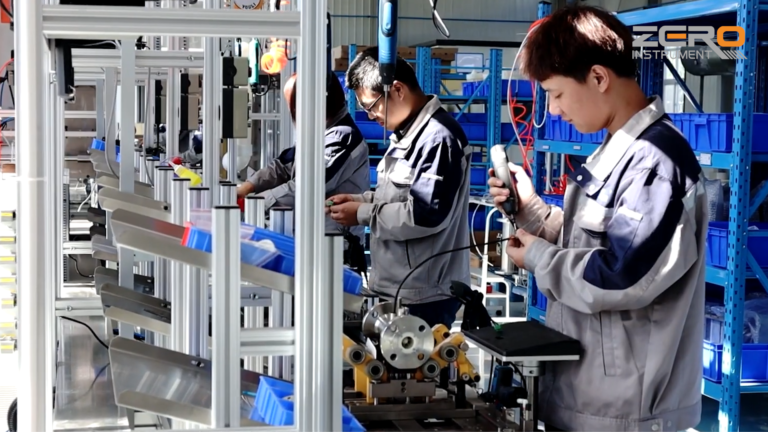
A reliable ceramic lined electromagnetic flowmeter selection process should follow a systematic sequence.
Step 1: Confirm that electromagnetic measurement is suitable
Check electrical conductivity, pipe conditions, gas content, minimum flow, and maximum flow.
Step 2: Evaluate chemical compatibility
Identify all process chemicals, including HF, fluoride compounds, pH, concentration, temperature, and cleaning fluids.
Step 3: Evaluate abrasion and corrosion together
Review actual flow velocity, particle size, particle shape, solid concentration, and combined chemical effects.
Step 4: Verify the specific model’s operating limits
Confirm process temperature, thermal shock limitations, pressure, minimum absolute pressure, nominal diameter, and ambient temperature.
Step 5: Review the complete wetted-material system
Check electrodes, grounding components, seals, gaskets, and mechanical connections.
Step 6: Confirm installation and maintenance requirements
Evaluate pipe support, vibration, flange alignment, full-pipe conditions, and maintenance accessibility.
Step 7: Obtain written manufacturer confirmation
The final selection should be based on the actual construction, material specifications, and verified operating limits rather than a general statement that the flowmeter has ceramic lining.
9. Information Required for Ceramic Flowmeter Selection
To evaluate a ceramic lined electromagnetic flowmeter accurately, engineers and procurement teams should prepare the following information:
| Parameter | Required Information |
|---|---|
| Medium | Actual liquid or slurry composition |
| Pipe size | DN or actual internal diameter |
| Flow rate | Minimum, normal, and maximum |
| Temperature | Normal and maximum process temperature |
| Pressure | Normal and maximum operating pressure |
| Vacuum | Minimum absolute pressure, if applicable |
| Solids | Concentration and particle size distribution |
| Abrasion | Particle hardness, shape, and mineral composition |
| Chemistry | pH, chemical concentration, and fluoride content |
| Conductivity | Electrical conductivity of the medium |
| Connections | Flange standard and pressure rating |
| Output | 4-20 mA, pulse, HART, Modbus, or other requirements |
| Protection | Required IP rating and explosion protection, if applicable |
The more complete the process information, the more reliable the material selection and equipment recommendation will be.
10. Conclusion: Select the Complete Flowmeter, Not Just the Ceramic Liner
Ceramic lined electromagnetic flowmeters can provide valuable solutions for demanding industrial applications, particularly where abrasion resistance is important.
However, ceramic hardness, chemical resistance, and maximum material temperature should never be considered in isolation.
Reliable selection requires a complete evaluation of:
- Ceramic composition and construction
- Particle abrasion and flow velocity
- Chemical compatibility
- Temperature and thermal shock
- Operating pressure and vacuum
- Electrodes and sealing materials
- Installation and mechanical conditions
The most suitable flowmeter is not necessarily the one with the hardest ceramic or the highest advertised temperature rating. It is the one whose complete construction matches the actual process conditions.
Need help selecting a ceramic lined electromagnetic flowmeter?
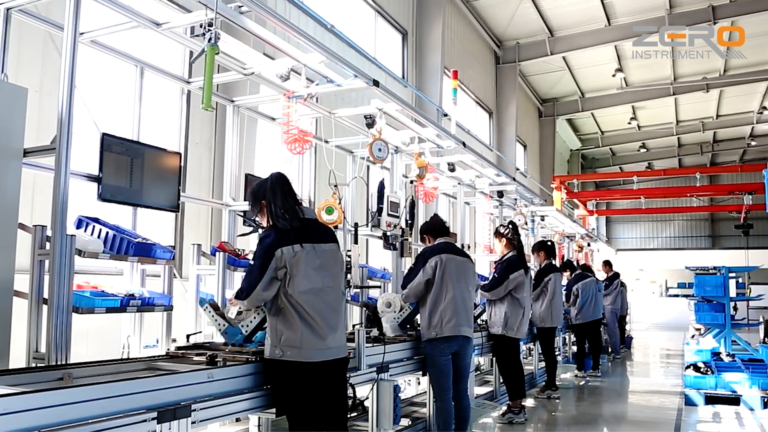
Zero Instrument provides electromagnetic flowmeter solutions for water treatment, mining, chemical processing, slurry measurement, and other industrial applications.
Send us your pipe size, medium composition, flow range, operating temperature, pressure, and particle characteristics. Our team can help evaluate suitable liner materials, electrode configurations, and flowmeter specifications for your application.
Contact Zero Instrument for technical assistance and a quotation.