
How Pressure and Temperature Compensation Prevents Hidden Errors in Industrial Steam Measurement
Imagine this situation: A factory’s monthly steam consumption report shows significantly more steam than the downstream production departments believe they have used.
The maintenance team inspects the steam pipelines. No obvious leaks are found. The vortex flowmeter passes its basic diagnostic checks. Its output remains stable, and its calibration records are still valid.
Yet the steam accounting figures do not match.
Where did the missing 17% go?
The answer may have nothing to do with a damaged flowmeter or a leaking pipeline. Instead, it may lie in a fundamental measurement issue: the difference between operating volumetric flow and mass flow.
A vortex flowmeter can measure volumetric flow correctly while the calculated steam mass flow is significantly inaccurate if pressure and temperature changes are not properly compensated.
Let’s examine why this happens and how modern integrated pressure and temperature compensation helps solve the problem.
1. The Mystery: When a Steam Flowmeter Reports the Wrong Mass Flow
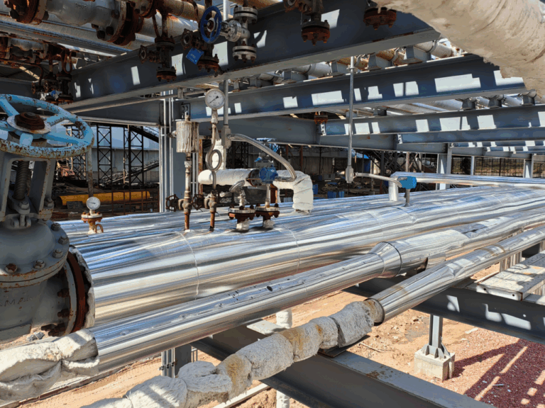
Consider a steam distribution pipeline operating under the following conditions:
- Steam pressure: 6 barg
- Steam temperature: 200°C
- Measurement technology: Vortex flowmeter
- Flow calculation: Fixed steam density
During normal production, the steam pressure decreases from 6 barg to 5 barg while the temperature remains approximately 200°C.
The vortex flowmeter continues measuring the operating volumetric flow.
However, if the flow calculation system still uses the density corresponding to 6 barg, the calculated mass flow will be incorrect.
Why?
Because steam density changes with pressure and temperature.
For a given operating volumetric flow, lower steam density means less mass passes through the pipeline per unit time.
If the measurement system does not recognize this change, it can report more steam mass than actually passes through the meter.
This creates an apparent discrepancy in steam consumption.
The steam has not necessarily disappeared. The measurement system may simply be using an outdated density value.
2. What Does a Vortex Flowmeter Actually Measure?
To understand the problem, we need to examine how vortex flowmeters work.
A vortex flowmeter uses the principle of the Kármán vortex street.
When steam flows past a bluff body installed inside the measuring tube, alternating vortices form downstream.
The frequency of these vortices is related to the flow velocity.
Within the meter’s calibrated operating range, the relationship can be expressed as:
[
f=\frac{v}{K_d}
]
Where:
- (f) = Vortex shedding frequency
- (v) = Average flow velocity
- (K_d) = Effective calibration-related proportionality factor
In practice, manufacturers use a calibrated meter factor to convert vortex frequency into volumetric flow.
The essential point is that vortex shedding directly provides information about flow velocity and operating volumetric flow, not steam mass flow.
Volumetric Flow Is Not Mass Flow
Operating volumetric flow describes how much space the steam occupies as it passes through the meter.
Mass flow describes how many kilograms of steam pass through the meter per unit time.
The relationship is:
[
\dot m=Q_v\times\rho
]
Where:
- (\dot m) = Mass flow rate, kg/h
- (Q_v) = Operating volumetric flow, m³/h
- (\rho) = Steam density at operating conditions, kg/m³
This equation explains why density compensation is important.
A vortex flowmeter can measure (Q_v) accurately, but if the density value used in the calculation is incorrect, the calculated mass flow will also be incorrect.
An analogy is counting railway carriages without knowing how many passengers are inside them.
Counting the carriages tells you something about the train, but it does not tell you the exact number of passengers.
Similarly, knowing the steam’s operating volume does not automatically tell you its mass.
3. How Can a Pressure Drop Create a 17% Error?
Let’s return to the original example.
Suppose the steam temperature remains constant at 200°C while the pressure decreases from 6 barg to 5 barg.
First, we must convert gauge pressure into absolute pressure.
Assuming atmospheric pressure of approximately 1 bar:
- Initial pressure: 6 barg ≈ 7 bara
- Actual pressure: 5 barg ≈ 6 bara
For a simplified illustration, assume steam behaves approximately as an ideal gas.
At constant temperature:
[
\rho\propto P_{\text{abs}}
]
Therefore:
[
\frac{\rho_{\text{initial}}}{\rho_{\text{actual}}}
\approx\frac{7}{6}
]
The resulting relative mass-flow overstatement is:
[
\text{Error}=
\left(\frac{7}{6}-1\right)\times100%
]
[
\boxed{\text{Error}\approx16.7%}
]
This explains where the headline’s approximately 17% discrepancy comes from.
What Does This Result Mean?
The calculation means that if a flow computer continues using the original density after the actual pressure has fallen, the calculated steam mass flow could be approximately 16.7% higher than the true mass flow under the simplified assumptions.
It does not mean that 17% of the steam has physically leaked or disappeared.
The distinction is important.
Furthermore, real steam does not always behave exactly like an ideal gas. More accurate calculations should use established steam property correlations, such as IAPWS-IF97.
The actual error will depend on operating pressure, temperature, steam condition, measurement configuration, and the density-compensation method.
Nevertheless, the example demonstrates a fundamental engineering lesson:
Even a properly functioning volumetric flowmeter can produce a substantial mass-flow calculation error when steam density changes and the compensation system does not follow those changes.
4. Why Pressure and Temperature Compensation Matters
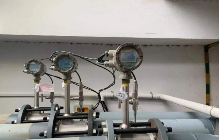
Steam systems rarely operate under perfectly constant conditions.
Pressure changes may occur because of:
- Variations in boiler output
- Changes in downstream steam demand
- Pressure-reducing valves
- Multiple production lines operating simultaneously
- Fluctuations in the steam distribution network
Temperature can also vary during startup, shutdown, load changes, and different operating conditions.
These variations influence steam properties and therefore affect the conversion from volumetric flow to mass flow.
Saturated Steam vs. Superheated Steam
The required compensation method depends on the steam condition.
Saturated steam
For dry saturated steam in thermodynamic equilibrium, saturation pressure and temperature are related.
Density can therefore be determined from an appropriate steam property model using either saturated pressure or saturation temperature.
However, this assumes the steam is dry and saturated. Significant moisture content can introduce additional measurement uncertainty that ordinary pressure or temperature compensation cannot eliminate.
Superheated steam
For superheated steam, pressure and temperature are independent operating variables.
Accurate density calculation therefore generally requires both measurements.
The mass flow can then be calculated using:
[
\dot m=Q_v\times\rho(P,T)
]
where (\rho(P,T)) is obtained from a suitable steam property calculation.
For industrial steam applications, the IAPWS-IF97 formulation is widely used for calculating thermodynamic properties.
Mass Flow and Heat Flow Are Not the Same
Steam mass flow is often used for production monitoring and consumption allocation.
However, energy accounting may require another calculation:
[
\dot E=\dot m\times h
]
Where:
- (\dot E) = Enthalpy flow rate
- (\dot m) = Steam mass flow rate
- (h) = Specific enthalpy
For useful heat delivered to a process, the relevant energy balance may also need to account for condensate return conditions and other system boundaries.
Therefore, accurate steam energy measurement requires more than simply measuring operating volumetric flow.
5. Traditional Steam Flow Measurement: Multiple Instruments, One Calculation
Conventional steam mass-flow measurement systems often use several separate devices.
A typical arrangement includes:
- A vortex flowmeter measuring operating volumetric flow
- A pressure transmitter measuring steam pressure
- A temperature transmitter or RTD measuring steam temperature
- A flow computer calculating steam density and mass flow
This arrangement remains widely used in industrial facilities.
It is flexible and can be appropriate for large plants with existing instrumentation and centralized control systems.
However, it also introduces several engineering considerations.
More Components and Installation Work
Separate instruments require additional process connections, cable routing, terminations, configuration, and maintenance.
Potential Signal and Configuration Errors
An incorrect pressure range, temperature signal, engineering unit, or flow-computer setting can affect the final result.
For example, confusing gauge pressure with absolute pressure can create substantial errors in density calculation.
Overall Measurement Uncertainty
The uncertainty of the complete mass-flow measurement system depends on more than the flowmeter itself.
It also includes pressure and temperature measurement, compensation algorithms, installation conditions, and instrument configuration.
A flowmeter with high standalone accuracy does not automatically guarantee equally high system-level mass-flow accuracy.
This leads to a practical question:
Can steam flow, pressure, temperature, and mass-flow calculation be integrated into a single instrument?
6. Integrated Pressure and Temperature Compensation: A More Compact Approach
Modern vortex flowmeters can combine several measurement and calculation functions within one device.
Depending on the model and configuration, an integrated solution may include:
- Vortex-based operating volumetric flow measurement
- Built-in temperature measurement
- Integrated pressure measurement
- Steam density calculation
- Compensated mass-flow output
- Steam energy calculation
- Digital communication with PLC, DCS, or monitoring systems
Instead of sending multiple signals to a separate flow computer, the instrument performs the relevant calculations internally.
How Integrated Compensation Works
The operating principle can be summarized in three steps.
Step 1: Measure volumetric flow
The vortex sensor determines operating flow from the vortex shedding frequency.
Step 2: Measure steam conditions
Integrated temperature and pressure sensors, where fitted, monitor the operating conditions.
Step 3: Calculate compensated flow
The transmitter uses the measured conditions and the appropriate steam property model to calculate density and output mass flow.
This approach reduces the need for separate compensation equipment and simplifies system architecture.
Does Integration Improve Accuracy?
Integration can reduce certain error sources, particularly those associated with external signals, inconsistent configuration, and additional interfaces.
However, integration alone does not guarantee better accuracy in every installation.
Measurement performance still depends on sensor specifications, calibration, operating conditions, installation quality, and the manufacturer’s stated system uncertainty.
A properly engineered conventional compensation system can also deliver excellent results.
The advantage of integration is that more of the complete measurement system is engineered and configured as one coordinated package.
7. From Separate Instruments to Integrated Steam Measurement
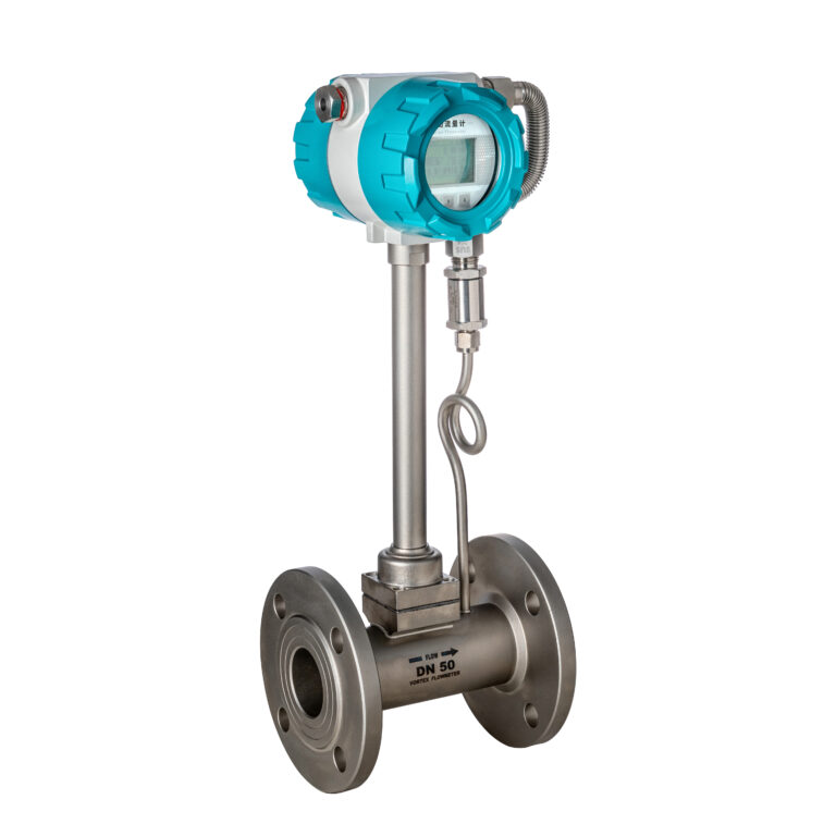
The development of vortex flow measurement has gradually moved beyond simple volumetric flow indication.
Earlier systems relied extensively on external temperature and pressure transmitters and separate flow computers.
Subsequent generations introduced built-in compensation functions, digital processing, integrated sensors, and additional energy measurement capabilities.
For example, KROHNE’s OPTISWIRL product family demonstrates this development.
The OPTISWIRL 4200 can be configured with integrated temperature measurement and optional integrated pressure measurement, allowing compensated mass-flow and energy calculations for relevant applications.
Such developments reflect a broader trend in industrial instrumentation:
The measuring instrument is increasingly becoming a complete measurement and calculation system rather than a standalone sensor.
Can an Integrated Flowmeter Reduce Costs?
Potential savings may include:
- Fewer external instruments
- Reduced wiring and installation labor
- Fewer process connections
- Simplified commissioning
- Lower equipment integration requirements
- Reduced maintenance complexity
For certain configurations, manufacturers have reported significant installation-cost savings compared with arrangements using separate transmitters and a flow computer.
However, the actual saving depends on the project.
A realistic comparison should consider the complete installed cost, not only the purchase price of the flowmeter.
For some facilities, an existing external compensation system may remain the most economical choice.
For new installations or compact measurement stations, an integrated solution may be particularly attractive.
8. Engineering Application: Steam Monitoring in an Industrial Plant
Consider a hypothetical manufacturing plant operating a central steam distribution network.
Several production workshops receive steam from a common boiler system.
The plant uses vortex flowmeters to monitor consumption and allocate steam costs among departments.
The Measurement Challenge
Steam pressure varies throughout the day as production demand changes.
Some measurement points use fixed density settings in their flow calculation systems.
Although the vortex flowmeters operate normally, the reported mass-flow values do not consistently reflect the changing steam conditions.
The discrepancies make departmental steam accounting difficult.
The Engineering Solution
The plant evaluates vortex flowmeters equipped with suitable pressure and temperature compensation.
The updated measurement arrangement allows mass flow to be calculated using steam properties corresponding to the actual operating conditions.
Where required, compensated mass-flow signals are transmitted to the plant monitoring system.
Expected Benefits
The improved measurement architecture can support:
- More consistent steam consumption records
- Better visibility of process demand
- More reliable allocation of steam costs
- Easier identification of genuine energy losses
- Improved data quality for energy management
These are expected engineering benefits rather than measured performance results from a documented installation.
Actual improvements should be verified through commissioning, comparison testing, and periodic measurement-system assessment.
9. Common Mistakes When Selecting a Steam Vortex Flowmeter
Selecting a vortex flowmeter with pressure and temperature compensation does not eliminate the need for proper engineering.
Several mistakes should be avoided.
Mistake 1: Assuming Every Vortex Flowmeter Measures Mass Flow Directly
Most conventional vortex flowmeters measure operating volumetric flow.
Mass flow requires density information or an appropriate compensation method.
Always confirm whether the specified instrument provides actual compensated mass flow or only volumetric flow.
Mistake 2: Confusing Gauge Pressure With Absolute Pressure
Steam property calculations generally require absolute pressure.
If an instrument is configured incorrectly, the resulting density calculation may be inaccurate even if the pressure sensor itself is operating properly.
Mistake 3: Using Saturated-Steam Compensation for Superheated Steam
A saturation-based density calculation may be inappropriate for superheated steam.
Confirm the actual steam condition and the compensation functionality supported by the instrument.
Mistake 4: Ignoring Low-Flow Limitations
Vortex flowmeters require sufficient flow velocity and vortex signal strength.
At low flow rates, especially under low-density steam conditions, the vortex signal may become too weak for reliable measurement.
The minimum measurable flow must be checked against the actual operating pressure, temperature, and pipe diameter.
Mistake 5: Overlooking Wet Steam
Wet steam can introduce additional errors because the flow contains both vapor and liquid droplets.
Ordinary pressure and temperature compensation cannot by itself determine steam dryness fraction or remove all two-phase-flow measurement errors.
Mistake 6: Neglecting Installation Conditions
Vortex flowmeters are sensitive to disturbed flow profiles, vibration, and certain forms of pulsation.
Adequate straight pipe lengths, suitable mounting arrangements, and appropriate process conditions remain important.
Manufacturer-specific installation requirements must always take precedence over general rules of thumb.
10. A Practical Selection Checklist
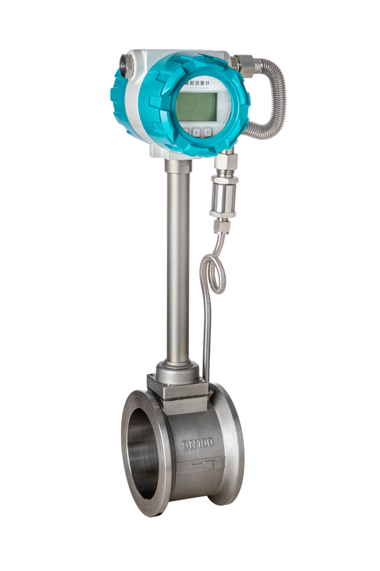
Before ordering a vortex steam flowmeter, confirm the following operating parameters.
| Parameter | Engineering Requirement |
|---|---|
| Steam condition | Saturated, superheated, or potentially wet |
| Pipe size | DN / NPS |
| Flow range | Minimum, normal, and maximum steam mass flow |
| Operating pressure | Minimum, normal, and maximum |
| Operating temperature | Normal and maximum |
| Required accuracy | Flow or complete compensated mass-flow system |
| Compensation method | Pressure, temperature, or combined P+T |
| Power supply | 24 VDC, AC, or other |
| Communication | 4–20 mA, pulse, HART, RS485, etc. |
| Process connection | Flanged or wafer type |
| Installation | Available straight lengths and pipeline configuration |
| Additional requirements | Hazardous-area approval, protection rating, energy calculation |
It is also important to confirm whether the specified pressure and temperature sensors are integrated into the quoted configuration.
Not every vortex flowmeter advertised as having temperature compensation includes an integrated pressure sensor.
Likewise, communication protocols, energy measurement functions, and available approvals can differ by model.
11. Accurate Steam Measurement Is an Energy Management Issue

Steam is one of the most important utilities in many industrial facilities.
It is used for heating, drying, sterilization, food processing, chemical production, textile manufacturing, and numerous other operations.
When steam measurement is inaccurate, the consequences can extend beyond a single flowmeter reading.
Unreliable data can affect production cost allocation, energy performance assessments, boiler efficiency analysis, and internal consumption reporting.
Better measurement does not automatically reduce steam consumption.
However, it provides a more reliable basis for identifying inefficiencies and making informed operational decisions.
For organizations managing energy performance or carbon emissions, dependable steam and heat measurement can also improve the quality of the underlying energy data.
Conclusion: The Missing 17% May Be a Calculation Error
Returning to our original mystery, the apparent 17% discrepancy does not necessarily indicate a steam leak, a defective vortex sensor, or a failed instrument.
It may simply result from using a fixed density when actual steam pressure and temperature have changed.
A vortex flowmeter measures operating volumetric flow. Reliable steam mass-flow measurement requires appropriate density compensation.
Traditional multi-instrument compensation systems remain valid and effective, but integrated pressure and temperature compensation offers an increasingly practical alternative for many industrial applications.
The most important lesson is simple:
A flowmeter can be working correctly while the overall flow calculation is wrong.
Before replacing a suspected faulty steam flowmeter, check whether its pressure, temperature, density, and mass-flow calculations accurately represent the actual process conditions.
Sometimes, the missing steam was never missing at all.
At Dalian Zero Instrument Technology Co., Ltd., we provide industrial flow measurement solutions for steam, gas, liquids, and process applications. Selecting a suitable vortex flowmeter requires careful consideration of flow range, operating pressure, temperature, compensation requirements, and installation conditions. Our team can assist with technical selection based on your application data.