
Engineers see this kind of problem all the time:
- The sensor LED is ON, but the PLC input never changes.
- The relay clicks normally, but the equipment refuses to start.
- A fire alarm system suddenly reports false alarms after wiring.
- Even worse — an input module burns out immediately after connection.
At first glance, these problems may look like PLC failures, defective sensors, or damaged modules.
But in many real industrial projects, the root cause is much simpler:
The dry contact and wet contact signals were misunderstood.
This is one of the most common and most overlooked problems in PLC systems, instrumentation, building automation, and fire alarm applications.
When wired correctly, everything works smoothly.
When wired incorrectly, troubleshooting can become extremely confusing.
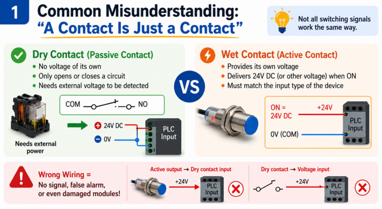
Common Misunderstanding: “A Contact Is Just a Contact”
Many technicians assume that if two wires become connected, a signal should automatically be detected.
That is only partially true.
Not all switching signals work the same way.
Some outputs are simply passive switch contacts.
They do not provide voltage themselves.
They only open or close an external circuit.
Other outputs actively provide voltage when activated, such as 24V DC outputs from sensors or controllers.
These two signal types require completely different wiring methods.
If the receiving device expects a dry contact but receives an energized voltage signal instead, the input module may be damaged.
If the receiving device expects a voltage signal but only receives a passive contact, the PLC may never detect the input.
That is why engineers should never judge a signal simply by the number of wires.
The key question is:
Does the signal provide its own voltage, or is it only a passive contact?
Relay Is Energized, But PLC Input Does Not Turn ON
This is one of the most typical field problems.
A relay clicking ON only means the relay coil is energized.
It does NOT guarantee that the PLC input receives a valid signal.
Many relay outputs are dry contacts.
The relay itself does not supply voltage to the PLC input.
The contact simply connects or disconnects an external circuit.
For example, if the PLC digital input requires 24V DC, a complete input loop must exist:
- 24V power supply
- Common terminal
- PLC input
- Relay contact
If only the relay contact is wired while the COM or power terminals are incorrect, the PLC input point will never turn ON.
This problem is especially common during panel retrofits and secondary wiring modifications.
Sensor LED Is ON, But Input Signal Is Wrong
Proximity switches, photoelectric sensors, and pressure switches are often misunderstood.
Many of them are not simple mechanical contacts.
Instead, they use:
- PNP outputs
- NPN outputs
- transistor switching outputs
These outputs do not simply “close a contact.”
They actively drive voltage or pull the signal to 0V.
If the PLC input type does not match the sensor output type, several strange problems may appear:
- PLC input never turns ON
- Input remains permanently ON
- Logic becomes reversed
- Signal becomes unstable or intermittent
This is why the sensor indicator LED alone is not enough for troubleshooting.
The LED only confirms target detection.
It does NOT guarantee compatibility with the PLC input module.
When troubleshooting, engineers should always verify:
- Sensor output type
- PLC input configuration
- COM terminal wiring
- 24V and 0V connections
Many field failures are ultimately caused by incorrect common terminal wiring.
False Alarms in Fire and Building Automation Systems
Dry and wet contact confusion is also extremely common in:
- Fire alarm systems
- Building automation systems
- Security systems
- Level alarm systems
Signals such as:
- Door switches
- Float switches
- Fault feedback contacts
- Running status signals
are often dry contacts.
If the control panel expects a passive dry contact but receives an energized voltage signal instead, the result may include:
- False alarms
- Communication errors
- Damaged input boards
Before wiring these systems, engineers should always carefully read the device documentation.
Typical keywords include:
Usually Dry Contact
- Dry contact
- Potential-free contact
- Relay output
- NO/NC contact
Usually Wet Contact or Powered Output
- Active output
- 24V DC output
- PNP output
- NPN output
- Transistor output
These descriptions are extremely important during commissioning.

How to Identify Dry Contact and Wet Contact
The safest method is always checking the manufacturer documentation.
Do not rely only on experience or assumptions.
Dry Contact Usually Means
- Relay contact output
- NO/NC contact
- Potential-free output
- Passive switch contact
These outputs do not generate voltage themselves.
Wet Contact Usually Means
- 24V DC output
- Active signal output
- PNP/NPN output
- Powered transistor output
These outputs actively provide voltage or current.
Practical Field Testing Method
If no documentation is available, a multimeter can help.
Testing Dry Contact
Disconnect external wiring first.
Use resistance or continuity mode.
If the contact only changes between OPEN and CLOSED states without generating voltage, it is most likely a dry contact.
Testing Wet Contact
Power the device normally.
Measure voltage between the output terminal and COM terminal.
If the output generates:
- 24V DC
- 12V DC
- or another rated voltage
during activation, it is likely a wet contact or active output.
However, engineers should remember:
Seeing voltage does not automatically mean the device itself is generating the voltage.
Sometimes the voltage comes from the external control circuit.
The key question is:
Is the voltage internally generated by the device itself?

When Is Dry Contact Better?
Dry contact outputs are preferred when:
- Electrical isolation is required
- System voltages may vary
- Only ON/OFF status is needed
- The PLC or controller provides its own sensing voltage
Typical applications include:
- Relay contacts
- Push buttons
- Limit switches
- Alarm feedback contacts
Advantages include:
- Better isolation
- Flexible voltage compatibility
- Strong system compatibility
However, dry contacts still require an external detection circuit.
Without external power, the PLC cannot detect status changes.
When Is Wet Contact Better?
Wet contacts are more suitable when:
- The receiving device expects voltage input
- Sensors already provide standard output signals
- Simplified wiring is preferred
Typical examples include:
- Proximity sensors
- Photoelectric sensors
- PLC transistor outputs
- Active instrumentation outputs
When PNP/NPN types are matched correctly, wiring becomes very straightforward.
But wet contacts must never be connected blindly.
Engineers must verify:
- Voltage level
- AC or DC type
- Polarity
- COM terminal
- Input compatibility
Especially in PLC systems, PNP/NPN mismatch is one of the most common field wiring mistakes.

Final Thoughts
In many industrial projects, so-called PLC failures are actually signal compatibility problems.
Before replacing PLC modules, sensors, or controllers, engineers should first verify:
- Is the output powered or passive?
- Does the PLC expect sourcing or sinking input?
- Is the COM terminal wired correctly?
- Is the signal type compatible?
A simple misunderstanding between dry contact and wet contact can lead to:
- False alarms
- Unstable operation
- Intermittent signals
- Burned input modules
- Long troubleshooting delays
Understanding these basic signal types is one of the most important foundations of industrial automation troubleshooting.