
During plant commissioning, engineers often encounter a frustrating situation:
The pressure gauge is new.
The temperature sensor is new.
The flow meter has been factory calibrated.
Yet once the system starts running, the readings become unstable.
Flow fluctuates unexpectedly.
Pressure jumps up and down.
Temperature values no longer reflect the real process condition.
Many people first suspect instrument quality problems. But after inspection, the instruments themselves are usually fine.
In many cases, the real issue is the installation position.
The arrangement of pressure gauges, temperature sensors, flow meters, and valves inside a pipeline may look like a simple “which one goes first” problem. In reality, incorrect installation can seriously affect measurement stability, process control, alarms, interlocks, and even plant safety.
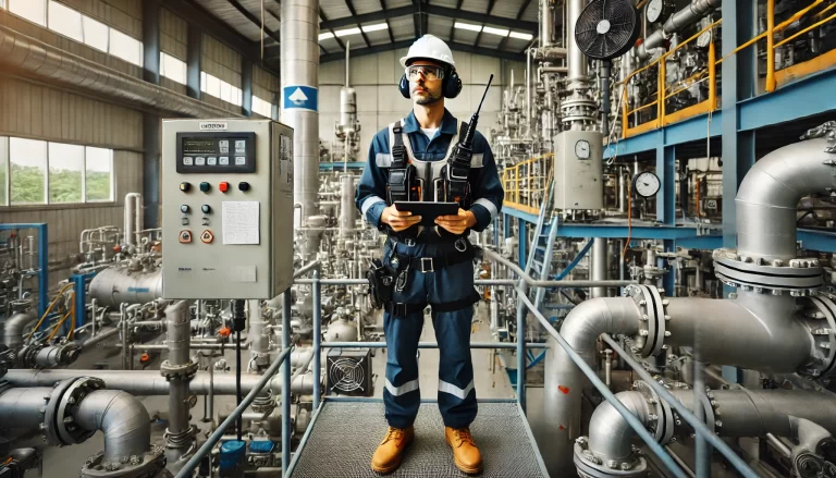
Overall Installation Philosophy
Many piping drawings show a typical arrangement like this:
Upstream Valve → Pressure Gauge → Temperature Sensor → Flow Meter → Downstream Valve
This arrangement is not completely wrong, but it should never be treated as a universal rule.
Industrial pipelines are not all the same.
Liquids, gases, and steam behave differently.
Electromagnetic, vortex, turbine, ultrasonic, and Coriolis flow meters also have different installation requirements.
The key point is:
Instrument installation is not about which device comes first — it is about which device affects the others.
Valves, elbows, reducers, tees, pump outlets, and compressor outlets all disturb the flow profile.
Flow meters are especially sensitive to unstable flow conditions. Once the upstream flow becomes turbulent, measurement stability can quickly deteriorate.
Before deciding instrument positions, engineers should first evaluate:
- Process medium
- Flow meter type
- Pressure and temperature compensation requirements
- Available straight pipe length
- Vibration conditions
- Maintenance accessibility
Only after understanding these factors can a reliable installation layout be designed.

Do Not Install Valves Too Close to Flow Meters
Valves are one of the most common sources of flow disturbance in industrial pipelines.
This is especially true for:
- Control valves
- Globe valves
- Partially opened ball valves
- Butterfly valves
When throttling occurs, turbulence, swirl, and unstable velocity profiles are generated downstream.
If a flow meter is installed immediately after the valve, unstable readings are very likely.
Recommended Practice
Whenever possible:
Install control valves downstream of the flow meter.
This helps maintain a more stable upstream flow profile and improves measurement reliability.
Of course, plant space is sometimes limited, and valves cannot always be relocated.
If a valve must be installed upstream of the flow meter:
- Increase upstream straight pipe length
- Consider flow conditioning devices
- Follow manufacturer installation recommendations
The problem is usually not the valve itself — it is placing the valve too close to the flow meter.

Pressure Measurement Must Prevent Gas Pockets, Liquid Accumulation, and Blockage
Pressure measurement may appear simple, but unstable pressure readings are often caused by poor tapping point design or impulse line installation.
For Liquid Measurement
Gas bubbles trapped inside impulse lines can cause:
- Slow pressure transmission
- Unstable readings
- Measurement drift
For dirty, crystallizing, or sludge-containing fluids, low-point tapping locations may easily become blocked.
For Gas Measurement
The opposite problem occurs.
Condensation inside impulse lines can distort pressure readings.
This is common in:
- Wet gas
- Compressed air
- Process exhaust gas
Proper drainage and impulse line routing become extremely important.
For Steam Measurement
Steam applications require even more attention.
High-temperature steam should never directly contact pressure instruments.
Typical protection methods include:
- Siphon tubes
- Condensate loops
- Condensate pots
In cold climates, heat tracing and freeze protection must also be considered.
Otherwise, long-term reliability problems are very common.

Temperature Sensors Must Measure the Real Process Temperature
Many people underestimate temperature measurement.
A thermowell installed into the pipe does not automatically guarantee accurate temperature measurement.
One of the most common problems is insufficient insertion depth.
The sensor must reach the main flow region — not just the pipe wall area.
If the thermowell is inserted too shallowly, the sensor may only measure localized wall temperature instead of the actual process temperature.
Temperature sensors should also avoid locations where:
- Fluids are not fully mixed
- Pump discharge turbulence exists
- Electric tracing locally overheats the pipe
- Heat exchanger outlet temperatures are uneven
For small pipelines, angled installation may improve measurement quality.
For large steam pipelines with high flow velocity, thermowell strength and vibration calculations should also be evaluated carefully.
Having a temperature reading does not necessarily mean the measurement is accurate.
The actual sensing location determines whether the data is meaningful.

Flow Meters Have the Strictest Installation Requirements
Compared with pressure or temperature instruments, flow meters are much more sensitive to installation conditions.
A flow meter installed too close to:
- Elbows
- Valves
- Tees
- Reducers
- Pumps
will often produce unstable readings.
Before checking flow meter accuracy specifications, engineers should first confirm whether the installation conditions are suitable.
Important considerations include:
- Upstream and downstream straight pipe length
- Flow disturbance
- Full pipe condition
- Vibration
- Pulsation
- Air bubbles
- Condensation
Different flow meter technologies also have different priorities.
| Flow Meter Type | Typical Installation Concern |
|---|---|
| Electromagnetic Flow Meter | Requires full pipe condition |
| Vortex Flow Meter | Sensitive to vibration and turbulence |
| Turbine Flow Meter | Sensitive to flow profile and cleanliness |
| Orifice Plate | Requires strict straight pipe conditions |
| Coriolis Mass Flow Meter | Sensitive to vibration and piping stress |
| Ultrasonic Flow Meter | Sensitive to bubbles and flow profile |
Typical straight pipe recommendations may include:
- Electromagnetic: 5D upstream / 3D downstream
- Vortex: 15D upstream
- Turbine: 20D upstream
- Orifice plate: up to 30D upstream depending on disturbance
Actual requirements should always follow manufacturer recommendations.
Liquid, Gas, and Steam Applications Must Be Evaluated Separately
Liquid Applications
Key concerns include:
- Full pipe condition
- Air bubbles
- Cavitation risk
Flow meters should preferably be installed:
- At low points
- In upward-flow sections
- Where back pressure remains stable
Avoid installing them at high points or partially filled downward-flow sections.
Gas Applications
Main concerns include:
- Pulsation
- Condensation
- Pressure fluctuation
Compressed gas systems, compressor outlets, and downstream control valves often create unstable flow conditions.
Maintenance accessibility and condensate drainage should also be considered.
Steam Applications
Steam measurement is usually the most demanding.
Engineers must consider:
- High temperature
- Condensate
- Steam quality
- Pressure and temperature compensation
- Vibration
Pressure instruments require condensate protection.
Temperature sensors require properly designed thermowells.
Flow meters should avoid low points where condensate accumulates.
For saturated steam systems, steam dryness and compensation accuracy can significantly affect energy calculations.
A More Reliable Instrument Installation Strategy
When designing a new process pipeline, it is often better to determine the flow meter position first.
This is because flow meters usually have the strictest installation requirements.
Choose locations with:
- Stable flow profile
- Minimal vibration
- Adequate straight pipe length
- Convenient maintenance access
Then determine valve positions.
Control valves should preferably remain downstream of the flow meter whenever possible.
Pressure and temperature tapping points should then be arranged according to:
- Measurement purpose
- Compensation requirements
- Maintenance accessibility
- Manufacturer recommendations
Finally, practical maintenance issues should also be considered:
- Can root valves be operated easily?
- Can transmitters be removed safely?
- Can thermowells be extracted?
- Is there enough maintenance space?
- Are drainage, venting, heat tracing, and freeze protection considered?
Good piping drawings do not always guarantee good field performance.
Instrument installation is ultimately not a “component order” problem — it is a process condition matching problem.
Final Thoughts
Instrument quality is important, but installation position is equally critical.
- Pressure measurement must avoid gas pockets, liquid accumulation, and blockage
- Temperature measurement must represent the true process condition
- Flow meters require stable flow profiles
- Valves should not disturb upstream measurement conditions
Correct installation creates stable systems.
Incorrect installation often leads to endless troubleshooting, unstable operation, false alarms, and wasted maintenance effort.
Need Help Selecting the Right Installation Arrangement?
Different industrial applications require different installation solutions depending on:
- Medium
- Pipe size
- Flow range
- Pressure and temperature
- Valve location
- Pump or compressor position
- Available straight pipe length
We can help recommend suitable installation solutions for:
- Electromagnetic flow meters
- Vortex flow meters
- Turbine flow meters
- Coriolis mass flow meters
- Ultrasonic flow meters
- Pressure and temperature instruments
Contact us for technical support and quotation.