During pipeline installation, one of the most common questions from field engineers is:
“Can we simply weld the flow meter directly onto the pipeline?”
Although welding may seem like a quick and convenient installation method, it is generally not recommended for most flow meters.
The reason is simple: flow meters are precision measuring instruments, and welding introduces high temperature, thermal stress, and mechanical deformation that may affect measurement accuracy and equipment reliability.
This article explains why most flow meters should not be welded directly, which types may allow welding under certain conditions, and what installation methods are recommended.
Why Welding Can Damage Flow Meters
Flow meters contain precision components such as:
Sensors
Electronic circuits
Coils
Electrodes
Pressure-sensitive elements
Mechanical moving parts
During welding, the arc temperature can reach several thousand degrees Celsius. The heat generated in the heat-affected zone may exceed the allowable temperature limits of many internal components.
Potential problems include:
1. Thermal Damage
High temperatures may damage:
Electronic boards
Sensor elements
Sealing materials
Insulation layers
Once damaged, the flow meter may experience signal instability or complete failure.
2. Mechanical Deformation
Many flow meters rely on precise geometry to achieve accurate measurement.
Welding heat can cause:
Pipe deformation
Sensor distortion
Internal stress
These changes may affect calibration accuracy.
3. Calibration Shift
A flow meter is calibrated under controlled factory conditions.
After welding, changes in:
Material properties
Mechanical stress
Sensor position
may cause measurement deviation.
Welding Suitability of Different Flow Meter Types
1. Electromagnetic Flow Meter
Welding possibility: Possible under controlled conditions
Electromagnetic flow meters are relatively more suitable for welding compared with other technologies because:
No moving mechanical parts
Metal measuring tube construction
Sensor and transmitter can be separated in remote versions
However, direct welding of a complete flow meter is still not recommended.
Recommended precautions:
Remove the transmitter and electronic components before welding
Control welding heat input
Avoid overheating the liner and electrodes
Perform insulation and leakage tests after installation
For large diameter pipelines (such as DN200 and above), some customized installations may consider welding-related solutions, but the manufacturer’s approval should always be obtained.
A differential pressure flow measurement system consists of two parts:
Primary Element
Examples:
Orifice plate
Venturi tube
Averaging pitot tube
These components are usually metallic and may be welded into the pipeline.
However, welding deformation must be controlled because it can affect:
Bore diameter
Flow coefficient
Measurement accuracy
Differential Pressure Transmitter
The transmitter itself must never be welded.
The transmitter should be connected through:
Impulse tubing
Three-valve manifold
Condensate pots (if required)
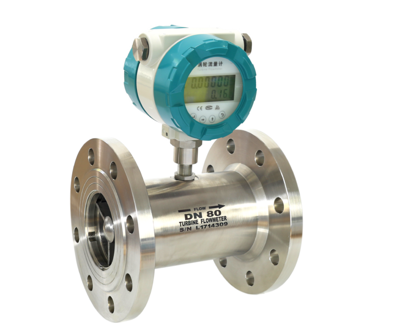
6. Turbine Flow Meter
Welding possibility: Not recommended
Turbine flow meters contain:
Precision bearings
Rotating impellers
Magnetic pickup sensors
Welding heat may cause:
Bearing lubrication failure
Magnetic component damage
Impeller imbalance
Recommended installation:
✅ Flange connection ✅ Thread connection for small sizes
7. Thermal Mass Flow Meter
Welding possibility: Not recommended
Thermal mass flow meters operate based on heat transfer principles.
Their key components include:
Heating elements
Temperature sensors
Welding heat can change:
Sensor characteristics
Electrical resistance values
Calibration parameters
As a result, the instrument may require recalibration.
Flow Meter Welding Suitability Comparison
Flow Meter Type
Welding Recommendation
Main Risk
Electromagnetic Flow Meter
Possible with strict control
Liner and electrode overheating
Coriolis Mass Flow Meter
Not recommended
Zero drift and tube deformation
Vortex Flow Meter
Not recommended
Sensor damage
Turbine Flow Meter
Not recommended
Bearing and impeller damage
Clamp-On Ultrasonic
No welding required
—
Insertion Ultrasonic
Mounting base can be welded
Sensor protection required
DP Flow Meter
Primary element may be welded
Deformation affects accuracy
Recommended Alternatives to Welding
For most applications, the following connection methods are preferred:
Flange Connection
The most common and reliable method.
Advantages:
Easy maintenance
Good pressure capability
Suitable for most industrial applications
Wafer Connection
Common for:
Vortex flow meters
Electromagnetic flow meters
Advantages:
Compact design
Lower installation cost
Thread Connection
Suitable for:
Small diameter pipelines
Low-pressure applications
Clamp Connection
Common in:
Food industry
Pharmaceutical applications
Hygienic systems
If Welding Is Absolutely Necessary
When site conditions require welding, follow these practices:
Before Welding
Remove electronic modules and transmitters
Protect sensitive components
Clean the pipeline
Confirm welding procedure with the manufacturer
During Welding
Use controlled heat input
Avoid continuous high-temperature heating
Monitor temperature near the instrument
Reduce thermal stress
After Welding
Perform:
Visual inspection
Pressure/leak test
Electrical insulation test
Calibration verification
Conclusion
Most flow meters should not be welded directly to pipelines because welding introduces excessive heat, mechanical stress, and potential calibration changes.