
A vortex flow meter that suddenly starts displaying unstable readings can create serious problems in industrial operations. Flow values may jump unexpectedly, oscillate during otherwise steady operation, or even indicate flow when the pipeline is supposed to be shut down.
The immediate reaction is often to suspect a faulty sensor or transmitter.
However, unstable vortex flow measurement does not necessarily mean the instrument is defective. Installation conditions, mechanical vibration, electrical interference, process fluctuations, and incorrect configuration can all produce similar symptoms.
Replacing the flow meter without identifying the actual cause may leave the problem unresolved.
This guide explains seven practical troubleshooting checks that maintenance engineers and instrumentation technicians should perform before deciding to replace a vortex flow meter.
1. Understanding Why Vortex Flow Meters Are Sensitive to Disturbances
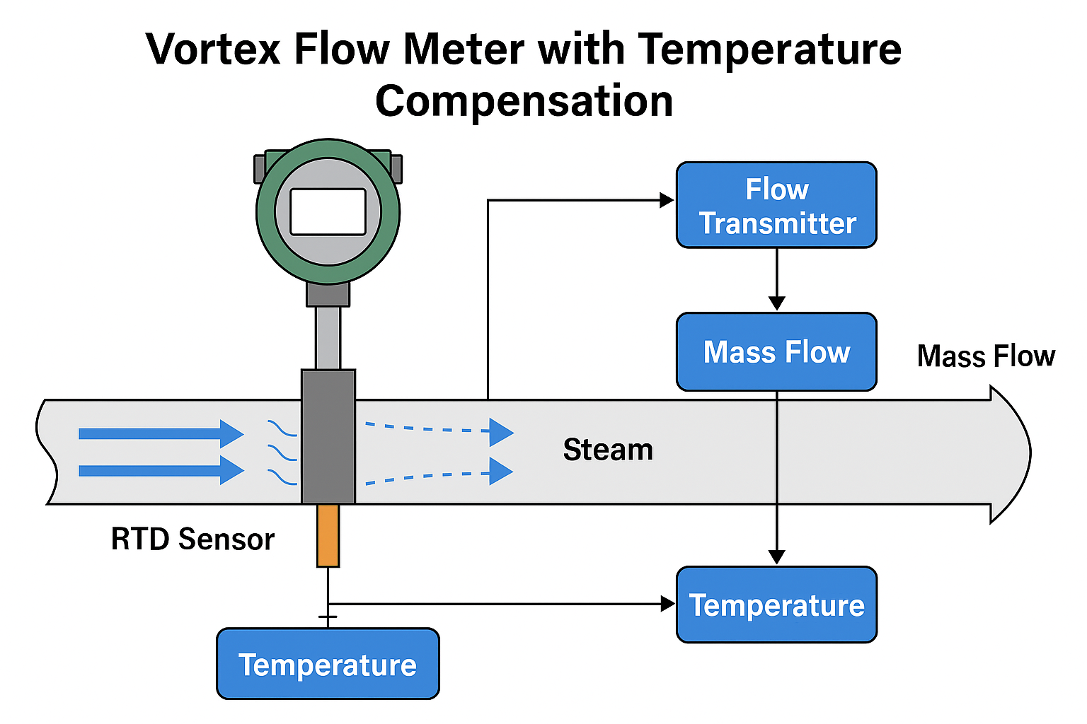
A vortex flow meter operates on the principle of the Kármán vortex street.
When fluid passes a bluff body, also called a vortex shedder, alternating vortices form downstream. Within the instrument’s specified operating range, the vortex shedding frequency is approximately proportional to flow velocity.
The relationship is commonly expressed as:
f = St × V / d
Where:
- f = Vortex shedding frequency (Hz)
- St = Strouhal number
- V = Fluid velocity (m/s)
- d = Characteristic width of the bluff body (m)
The instrument detects the shedding frequency and converts it into volumetric flow rate using its calibration characteristics.
This measurement method is widely used for steam, liquids, and industrial gases because vortex flow meters have no moving mechanical parts.
However, vortex shedding must remain sufficiently stable and detectable.
Disturbed flow profiles, mechanical vibration, excessive process pulsation, and electrical noise can interfere with the detected signal.
The critical troubleshooting question is whether the displayed fluctuation represents a real change in flow or a measurement disturbance.
2. Insufficient Straight Pipe Length and Disturbed Flow Profiles
One of the first things to inspect is the piping arrangement around the flow meter.
Vortex flow meters require appropriate upstream and downstream straight pipe lengths to maintain suitable flow conditions at the vortex shedder.
Elbows, reducers, expanders, control valves, and other piping components can introduce:
- Asymmetric velocity profiles
- Swirling flow
- Increased turbulence
- Flow separation
- Unstable vortex shedding
These disturbances may affect the accuracy and repeatability of the measurement.
Typical Straight Pipe Requirements
The actual requirements depend on the manufacturer’s design and the upstream piping configuration.
For example, Yokogawa’s VY Series provides the following installation guidance:
| Upstream piping condition | Upstream length | Downstream length |
|---|---|---|
| Straight pipe | 10D | 5D |
| Single 90° elbow | 10D | 5D |
| Double elbows in the same plane | 10D | 5D |
| Double elbows in different planes | 20D | 5D |
| Upstream reducer | 5D | 5D |
| Upstream expander | 10D | 5D |
| Upstream valve, where unavoidable | 20D | 5D |
Here, D represents the relevant internal pipe diameter.
These values are specific to the referenced VY Series and should not be treated as universal requirements for every vortex flow meter.
Always follow the installation instructions for the actual instrument model.
Why Control Valve Location Matters
A partially opened control valve can create substantial flow disturbance and pressure fluctuations.
If installed too close upstream of a vortex flow meter, these disturbances may reduce measurement stability.
Where possible, locate throttling control valves downstream of the flow meter, maintaining the recommended separation distance.
Recommended Field Checks
- Measure the available upstream and downstream straight pipe lengths.
- Check the distance to nearby elbows, valves, and reducers.
- Inspect pipe alignment and gasket positioning.
- Confirm that no gasket or internal step protrudes into the flow path.
- Compare the installation with the manufacturer’s piping requirements.
If the installation cannot meet the recommended straight pipe lengths, consult the manufacturer about approved alternatives.
A flow conditioner may be useful in certain applications, but it is not a universal substitute for adequate straight pipe length.
3. Mechanical Vibration and False Flow Signals
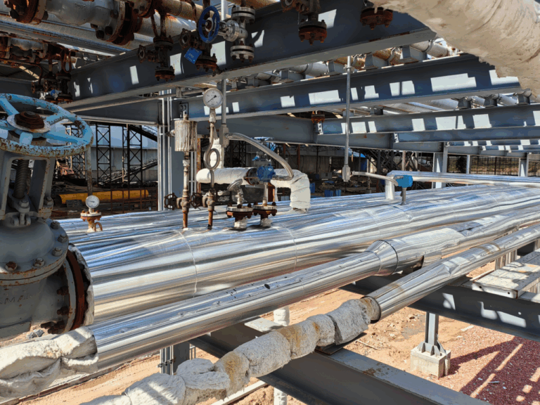
Mechanical vibration is another important cause of unstable vortex flow measurement.
Many vortex flow meters use sensors that detect small forces or pressure variations associated with vortex shedding.
External vibration from pumps, compressors, motors, and connected pipelines can interfere with these measurements.
Under certain conditions, the instrument may interpret mechanical vibration as a vortex signal.
Why Does a Vortex Flow Meter Show Flow When There Is No Flow?
Consider a compressed-air pipeline where the isolation valve has been closed.
The operator expects the flow reading to return to zero, but the transmitter continues displaying a small fluctuating flow rate.
Possible causes include:
- Mechanical vibration transmitted through the pipeline
- Electrical interference
- Incorrect low-flow or signal-processing settings
- Leakage through an isolation valve
- Actual residual or intermittent flow
Mechanical vibration becomes particularly important when its frequency overlaps the frequency range used to detect vortex shedding.
At low flow rates, the useful vortex signal may be relatively weak, making interference more noticeable.
How to Identify Vibration-Related Problems
Check whether the abnormal readings coincide with the operation of nearby equipment.
For example:
- Does the reading fluctuate when a compressor starts?
- Does the signal become unstable at certain pump speeds?
- Does the indicated flow persist when actual flow has been positively confirmed as zero?
- Does the measured shedding frequency remain nearly constant despite changes in process flow?
Where supported, use the transmitter’s diagnostic functions to monitor shedding frequency, signal strength, and signal quality.
These observations can help distinguish mechanical interference from actual process fluctuations.
Corrective Actions
Depending on the installation, corrective actions may include:
- Improving pipe support near the flow meter
- Investigating excessive vibration from pumps or compressors
- Correcting loose or inadequate pipe supports
- Avoiding installation near strong vibration sources
- Reviewing the manufacturer’s vibration limits
- Adjusting signal-processing parameters after confirming the cause
Flexible connectors and vibration isolation components should only be installed after evaluating their suitability for the pipeline, operating pressure, temperature, and mechanical loading.
Improper modifications may introduce additional vibration or piping stress.
4. Electrical Interference, Grounding, and Signal Cable Problems
Not every unstable flow reading originates from the hydraulic or mechanical system.
Electrical interference can also affect vortex flow meter signals, particularly in installations involving remote transmitters or long signal cable runs.
Common interference sources include:
- Variable frequency drives (VFDs)
- Large electric motors
- Contactors and switching equipment
- High-current power cables
- Inadequate cable shielding
- Poor grounding or equipotential bonding
- Incorrect signal cable connections
VFD-Related Interference
A common troubleshooting scenario occurs when a vortex flow meter becomes unstable whenever a nearby motor operates through a variable frequency drive.
The instrument may experience noise coupled into its sensor or signal wiring.
However, it is important not to assume that every flow fluctuation occurring during VFD operation is electrical interference.
Changes in motor speed may also produce real changes in pump output, flow velocity, and pressure.
How to Check Electrical Interference
Start by examining whether the fluctuation is visible on the transmitter itself or only in the PLC or control system.
If the local transmitter display is stable but the PLC reading fluctuates, investigate the output circuit, analog input configuration, wiring, and control-system scaling.
If both readings fluctuate, further investigation of sensor signals, operating conditions, and transmitter configuration is required.
Recommended checks include:
- Inspect signal and power cable routing.
- Ensure suitable separation from high-current cables.
- Verify cable shielding according to the manufacturer’s instructions.
- Check grounding and equipotential bonding.
- Inspect terminal connections for looseness, moisture, or corrosion.
- Confirm that the power supply and output wiring meet instrument requirements.
There is no single universal shield-grounding arrangement or grounding resistance value that applies to every vortex flow meter installation.
Follow the manufacturer’s wiring instructions and applicable electrical and EMC requirements.
5. Process Conditions: Wet Steam, Pulsation, and Two-Phase Flow
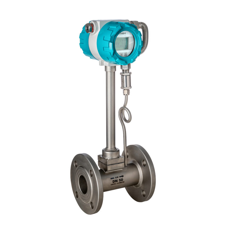
Some unstable readings are caused by the process itself rather than an installation defect or electronics failure.
This is particularly important in steam systems, compressed-air networks, and liquid applications operating near the limits of the flow meter.
Wet Steam and Condensate
Vortex flow meters are widely used for steam measurement, but excessive condensate or liquid entrainment can affect measurement stability.
Possible problems include:
- Unstable flow patterns
- Intermittent liquid slugs
- Pressure fluctuations
- Water hammer
- Reduced measurement accuracy
For steam applications, inspect steam quality, insulation, drainage, steam traps, and the flow meter’s installation orientation.
Do not assume that a fluctuating steam flow indication is automatically a sensor problem.
Opening a sensor compartment is not a routine solution to wet-steam measurement problems. Any inspection involving pressure boundaries or electrical enclosures must follow the manufacturer’s instructions and the plant’s isolation procedures.
Flow Pulsation
Reciprocating compressors, positive-displacement pumps, and rapidly operating control valves may generate pulsating flow.
Even if the average flow rate remains relatively stable, instantaneous flow velocity may vary significantly.
The vortex flow meter may respond to these actual changes, creating an oscillating indication.
Signal damping may reduce the visible fluctuation but does not eliminate the underlying process pulsation.
Low Flow and Reynolds Number Limitations
Every vortex flow meter has a minimum measurable flow range.
At low velocities, vortex shedding may become too weak or insufficiently stable for reliable detection.
In addition, changes in fluid properties and Reynolds number may affect the operating characteristics of the meter.
Typical symptoms include:
- Intermittent readings at low flow
- Unexpected zero readings
- Unstable frequency detection
- Increasing measurement uncertainty near the lower operating limit
Before changing transmitter settings, confirm that the expected minimum operating flow is within the manufacturer’s specified measurable range.
6. Low-Flow Cutoff, Filtering, and Signal Damping
If installation, vibration, electrical interference, and process conditions have been checked, the next step is to review the transmitter configuration.
Modern vortex flow meters may provide several signal-processing functions intended to improve measurement stability.
Low-Flow Cutoff
Low-flow cutoff forces the displayed flow to zero when the measured value falls below a configured threshold.
This function can help suppress unwanted low-level indications under certain conditions.
However, an excessively high cutoff setting may suppress genuine low flow.
This is especially important in steam and compressed-air energy monitoring, where undetected low flow can cause systematic under-registration of consumption.
The cutoff should therefore be selected based on the actual measurable range, process conditions, and manufacturer guidance rather than a fixed percentage applied to every instrument.
Signal Filtering
Signal filtering can help reject unwanted frequency components.
Some vortex transmitters provide adjustable trigger levels, frequency filters, or automatic signal-processing functions.
Incorrect adjustments can cause additional problems, including failure to detect real low-flow signals.
When available, examine diagnostic information such as vortex shedding frequency and signal strength before changing filter settings.
Damping Time
Damping smooths the displayed or transmitted flow signal.
Increasing damping can make the indication appear more stable, but it also slows the instrument’s response to genuine flow changes.
For monitoring applications, moderate damping may be acceptable.
For fast process control, excessive damping can adversely affect control performance.
Filtering and damping should never be used simply to hide an unresolved mechanical or process problem.
Record the original configuration before making changes, and evaluate the effect of each adjustment under representative operating conditions.
7. Practical Vortex Flow Meter Troubleshooting Checklist
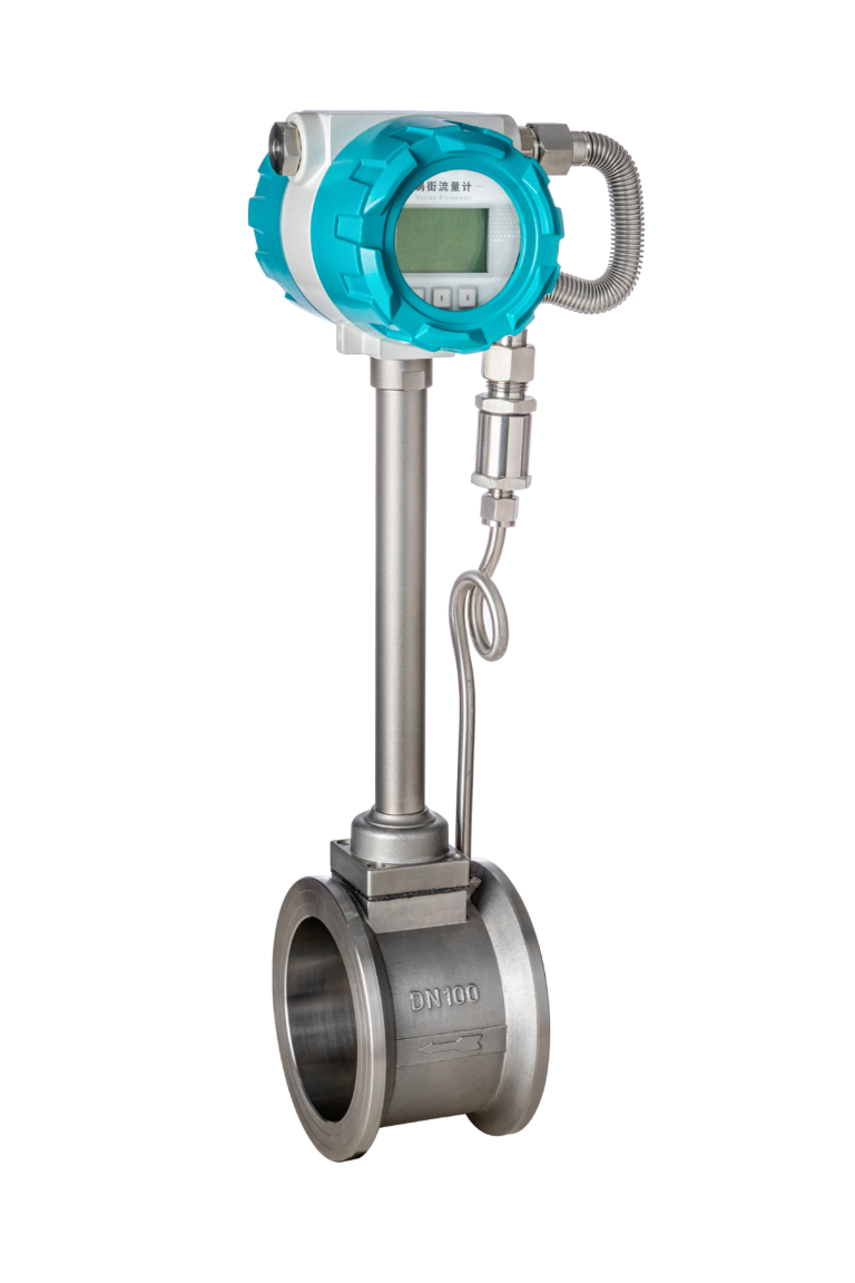
A structured troubleshooting sequence helps avoid unnecessary instrument replacement and reduces maintenance time.
| Symptom | Possible cause | Recommended check |
|---|---|---|
| Reading fluctuates during steady operation | Flow disturbance or process pulsation | Check piping layout and process trends |
| Reading remains above zero after shutdown | Vibration, leakage, or electrical noise | Verify actual zero flow and review frequency signal |
| Signal becomes unstable when a pump starts | Mechanical vibration or real flow pulsation | Compare pump operation with flow trend |
| Reading changes when a VFD operates | Electrical interference or changing process conditions | Check wiring and process variables |
| Reading is unstable only at low flow | Weak vortex signal or incorrect configuration | Verify minimum measurable flow |
| Steam reading fluctuates intermittently | Wet steam or condensate carryover | Inspect steam quality and drainage |
| PLC value fluctuates but local display is stable | Output circuit, wiring, or PLC input issue | Inspect signal loop and input scaling |
| Reading is consistently incorrect | Incorrect configuration or disturbed flow profile | Verify K-factor, sizing, fluid settings, and installation |
Recommended Troubleshooting Sequence
Step 1 — Confirm the problem
Compare the flow meter indication with independent process information, such as pump status, valve position, pressure, and flow trends.
Determine whether the problem is genuine fluctuation, incorrect scaling, or false flow indication.
Step 2 — Inspect the installation
Check straight pipe lengths, nearby fittings, pipe alignment, installation orientation, and the manufacturer’s requirements.
Step 3 — Investigate mechanical vibration
Examine pipe supports and compare abnormal readings with pump, compressor, or motor operation.
Step 4 — Check electrical connections
Inspect cable routing, shielding, grounding, power supply, and signal wiring.
Step 5 — Verify process conditions
Check actual flow range, steam quality, fluid properties, pressure fluctuations, and possible two-phase flow.
Step 6 — Review transmitter configuration
Verify the calibration factor, fluid settings, low-flow cutoff, filtering, damping, and other model-specific parameters.
Step 7 — Evaluate the instrument hardware
Only after the preceding checks should sensor damage, electronics failure, or instrument replacement become the primary focus.
Follow manufacturer-approved diagnostic and maintenance procedures before replacing components.
8. When Should You Replace the Vortex Flow Meter?
Replacing the complete instrument is justified when troubleshooting confirms that its measurement performance cannot be restored through installation corrections, configuration adjustments, or approved maintenance.
Possible reasons include:
- Confirmed sensor or electronics failure
- Physical damage to the measuring element
- Severe internal corrosion or erosion
- Persistent diagnostic faults
- Inability to meet the required operating range
- Incompatibility with the actual process conditions
In some cases, replacing only the transmitter electronics or an approved service component may be sufficient.
In other cases, an incorrectly sized meter or unsuitable measurement technology may require a complete redesign.
For example, where minimum flow is consistently below the vortex meter’s specified operating range, installing an identical replacement may not solve the problem.
The correct decision depends on the application, diagnostics, and process requirements.
Conclusion: Diagnose the Measurement System Before Replacing the Meter

A fluctuating vortex flow meter reading does not automatically indicate a defective instrument.
Insufficient straight pipe length, mechanical vibration, electrical interference, process pulsation, wet steam, and incorrect parameter settings can all contribute to unstable readings.
The most effective troubleshooting approach is systematic:
Verify the process, inspect the installation, investigate vibration, check electrical connections, review configuration, and evaluate the hardware only when necessary.
For maintenance engineers, this approach can reduce unnecessary replacement costs, minimize downtime, and improve long-term flow measurement reliability.
Most importantly, always distinguish between genuine process fluctuations and false measurement signals before applying corrective actions.
A stable display is useful, but an accurate and representative flow measurement is what the process actually needs.