
A low dew point reading does not necessarily mean that your entire instrument air system is safe from moisture-related problems.
Consider a common situation in an industrial plant.
An online dew point analyzer is installed at the outlet of the instrument air drying system. Its reading remains stable at −45°C throughout the year. During routine inspections, the instrument air system is repeatedly accepted as compliant.
However, when winter arrives, several pneumatic control valves begin to malfunction.
- The valve does not respond to small control signals.
- Large control signals cause sudden and excessive movement.
- The valve positioner repeatedly fails during auto-calibration.
- After disassembly, technicians discover moisture and oily deposits inside the precision pneumatic passages.
Is the dew point analyzer defective?
Not necessarily. The displayed reading may be perfectly correct.
The real problem may be that the measurement does not represent the actual moisture conditions throughout the instrument air system.
This article explains three common mistakes in dew point measurement, the relevant requirements of GB/T 4830-2015, and five practical steps for troubleshooting instrument air quality problems.
1. The First Question: Does a −45°C Reading Prove That Instrument Air Is Qualified?

The answer is: No, not by itself.
According to GB/T 4830-2015, Industrial Automation Instrument Air: Pressure Range and Quality, the dew point requirement is related to the minimum ambient temperature of the entire instrument air system.
Section 4.2 specifies that:
The dew point of instrument air under operating pressure must be at least 10°C lower than the minimum ambient temperature.
In other words:
Pressure Dew Point ≤ Minimum Ambient Temperature − 10°C
This means that a fixed dew point reading cannot independently determine whether an instrument air system meets the required conditions.
To evaluate compliance correctly, engineers must consider:
- The pressure at which the dew point is measured.
- The minimum ambient temperature throughout the system.
- The location of the measurement point.
These three factors are frequently overlooked during routine inspections.
2. Three Common Mistakes in Instrument Air Dew Point Measurement
2.1 Confusing Pressure Dew Point with Atmospheric Dew Point
One of the most important questions is whether the analyzer measures pressure dew point or atmospheric pressure dew point.
Pressure dew point (PDP) is the temperature at which water vapor begins to condense at the actual operating pressure of the compressed air.
Atmospheric pressure dew point refers to the dew point measured after the sample has been reduced to approximately atmospheric pressure.
These two measurements are not directly interchangeable.
When compressed air is depressurized, its water vapor partial pressure changes. Consequently, its dew point changes as well.
For the same air sample, the atmospheric pressure dew point is generally lower than the pressure dew point at the original operating pressure.
This is why simply releasing compressed air into a portable analyzer at atmospheric pressure may produce a misleadingly low dew point reading.
If the analyzer displays −45°C after depressurization, this does not automatically mean that the instrument air has a pressure dew point of −45°C.
The measurement pressure must always be identified. If atmospheric pressure measurements are used, an appropriate pressure correction or conversion method is required.
2.2 Using Today’s Ambient Temperature Instead of the Annual Minimum
This is another common mistake.
Section 4.2 of GB/T 4830-2015 establishes the dew point requirement based on the minimum ambient temperature.
Section 2.2 defines the minimum ambient temperature as the lowest temperature in the locations where the entire system is installed, including:
- The outlet of the air purification equipment.
- The instrument air distribution network.
- The instruments and pneumatic equipment.
This definition has several important implications.
First, engineers should not use the temperature on the day of inspection. They should consider the lowest expected ambient temperature during the relevant operating period.
Second, the temperature inside the compressor room is not necessarily representative of the entire system.
Outdoor pipelines, exposed pipe racks, instrument manifolds and pneumatic valve assemblies may experience much lower temperatures.
Third, the coldest location in the system must be considered when establishing the required dew point.
Example:
Assume the minimum ambient temperature in an industrial installation is −18°C.
According to the requirement:
Pressure Dew Point ≤ −18°C − 10°C
Therefore, the required pressure dew point is:
≤ −28°C
If the minimum ambient temperature is −20°C:
Required Pressure Dew Point ≤ −30°C
This explains why an instrument air system that appears acceptable during summer may experience moisture-related problems in winter.
A dew point reading of −45°C may look excellent, but engineers must first confirm that it represents the actual pressure dew point under operating conditions.
2.3 Measuring Only at the Dryer Outlet
Where is the dew point analyzer installed?
If it is located only at the outlet of the air dryer, it may not reveal the actual conditions at the far end of the instrument air network.
As compressed air travels through pipelines, several problems may occur:
- Temperature drops along exposed pipelines.
- Moisture condenses when local conditions reach the pressure dew point.
- Condensed water accumulates in low points and poorly drained sections.
- Corrosion and contamination may introduce additional particles into the system.
- Drainage failures allow liquid water to enter downstream equipment.
Therefore, the air quality at the dryer outlet does not necessarily represent the air quality at every instrument connection.
For a more reliable assessment, engineers should consider measurements at both the dryer outlet and representative downstream locations, particularly the most remote or coldest sections of the network.
3. What Does GB/T 4830-2015 Require?
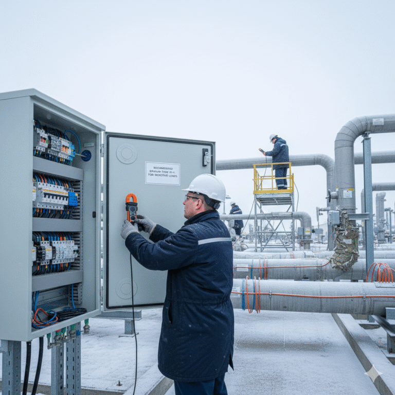
GB/T 4830-2015 specifies several important requirements for instrument air quality.
The main requirements discussed in this article are summarized below.
| Parameter | Standard requirement |
|---|---|
| Dew point | Pressure dew point ≤ minimum ambient temperature − 10°C |
| Solid particle size | ≤ 3 μm |
| Oil content | ≤ 10 mg/m³ |
The standard also specifies pressure ranges for the purification equipment outlet and nominal instrument inlet pressures.
For example:
- Section 3.1 specifies two outlet pressure ranges: 300–500 kPa and 500–800 kPa.
- Section 3.2.1 lists nominal instrument inlet pressures of 140, 260, 350, 550 and 700 kPa.
- Section 3.2.2 specifies an allowable pressure variation of ±10% of the nominal value.
Engineers should select the appropriate nominal pressure according to the instrument specifications and system design rather than assuming that any pressure within a seemingly reasonable range is acceptable.
For example, the nominal pressure ranges of 550 kPa ±10% and 700 kPa ±10% are:
- 550 kPa: 495–605 kPa.
- 700 kPa: 630–770 kPa.
A pressure of 600 kPa falls within the first range but not the second. The applicable nominal pressure must still be confirmed against the instrument design requirements.
4. A Tenfold Difference: 3 μm vs. 30 μm
This is an important detail that instrument engineers should not overlook.
According to Section 4.3 of GB/T 4830-2015, the solid particle size in instrument air must not exceed 3 μm.
However, Section 4.8.3 of GB/T 4213-2008, Pneumatic Control Valves, specifies the following air quality requirements for valves equipped with positioners:
- Solid particle content: less than 0.1 g/m³.
- Particle diameter: less than 30 μm.
- Oil content: less than 10 mg/m³.
The difference between 3 μm and 30 μm is a factor of ten.
These requirements appear in two different standards and should not be confused when specifying instrument air filtration.
For practical equipment selection, engineers should pay attention to the more stringent applicable air quality requirements.
Why does particle size matter?
Pneumatic valve positioners contain precision internal passages, restrictions and nozzle-flapper mechanisms.
Small particles can gradually accumulate in these passages, causing:
- Restricted airflow.
- Unstable pneumatic output.
- Slow response.
- Calibration difficulties.
- Positioning errors.
A filter being installed does not automatically mean that the air is adequately filtered.
Engineers should check the actual filtration rating, filtration efficiency, differential pressure and maintenance requirements of the filter element.
An important distinction: Common engineering recommendations such as a −40°C dew point or an oil content below 1 ppm should not automatically be presented as direct requirements of GB/T 4830-2015.
The standard’s dew point criterion is based on minimum ambient temperature, while its specified oil content limit is 10 mg/m³.
Always distinguish between mandatory standard requirements and additional project specifications or engineering recommendations.
5. Five Practical Steps to Troubleshoot Instrument Air Quality
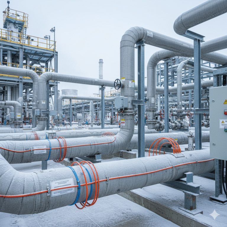
When pneumatic valves begin malfunctioning in winter, do not immediately replace the positioner.
Start by checking the instrument air supply.
Step 1: Inspect Filter Bowls and Drainage Points
Check the filter bowls on filter-regulator assemblies and instrument air distribution stations.
Look for:
- Accumulated water.
- Oil contamination.
- Rust particles.
- Sludge-like deposits.
Visible liquid water or oily contamination is a strong indication that the air treatment or drainage system requires investigation.
Step 2: Check the Downstream Pipeline
Inspect the drainage points at the far end of the instrument air network.
Open the drain carefully and observe whether water droplets, mist or oily contamination are discharged.
If the dryer outlet appears clean but water is found downstream, investigate pipeline cooling, low points, drainage arrangements and possible secondary condensation.
Step 3: Measure Dew Point at the Correct Pressure and Location
Confirm whether the dew point analyzer measures pressure dew point or atmospheric pressure dew point.
If a portable analyzer is used, ensure that the sampling arrangement and pressure correction method are appropriate.
At a minimum, consider checking:
- The dryer outlet.
- A representative downstream pipeline location.
- The coldest or most remote instrument air distribution point.
This provides a more realistic picture of the entire system.
Step 4: Use the Minimum Ambient Temperature as the Reference
Do not establish the dew point requirement based only on the current weather.
Determine the lowest expected ambient temperature at the relevant installation locations.
Then apply the criterion:
Required Pressure Dew Point ≤ Minimum Ambient Temperature − 10°C
A system that passes a summer inspection should not automatically be considered suitable for winter operation.
Step 5: Check Automatic Drain Valves
Automatic drainage systems are particularly important in low-temperature environments.
Water accumulated inside filter bowls and pipelines can freeze when temperatures fall below 0°C.
Ice may prevent drainage mechanisms from operating correctly, allowing liquid water to travel further downstream.
Depending on the installation, consider:
- Automatic or continuous drainage arrangements.
- Properly insulated or heated drainage components where appropriate.
- Periodic manual drainage inspections.
- Regular checks of drain valve operation.
The drainage system must be suitable for the actual operating environment.
6. What Happens When Instrument Air Quality Is Poor?
Contaminated instrument air does not necessarily cause an immediate instrument failure.
Instead, it often creates gradual problems inside pneumatic control systems.
Moisture can condense in pneumatic passages and may freeze when local temperatures fall below the relevant freezing conditions.
Oil mist and solid particles can accumulate inside precision restrictions, forming deposits that interfere with airflow.
The resulting problems may include:
1. Nozzle and flapper contamination
Particles and oily deposits restrict the precision pneumatic passages, affecting the positioner’s ability to regulate output pressure.
2. Slow response and positioning errors
The valve may fail to respond to small control signals or move excessively when the signal increases.
3. Auto-calibration failure
The positioner may repeatedly fail during automatic calibration because the pneumatic response is unstable.
4. Unstable control loops
The control valve may oscillate, respond slowly or fail to follow the controller output accurately.
5. Potential safety and process risks
If a control valve is required to perform an important protective function, poor pneumatic supply quality may affect its response when operation is required.
The most troublesome aspect is that these problems may not generate a direct instrument air quality alarm.
Instead, technicians may initially interpret the symptoms as a faulty positioner, a sticking valve stem or an unstable control loop.
The real cause may remain hidden in the instrument air supply for months.
7. Applicable Standards and Final Recommendations
The two main standards referenced in this article are:
GB/T 4830-2015 – Industrial Automation Instrument Air: Pressure Range and Quality
Relevant sections:
- Section 2.1: Definition of operating pressure.
- Section 2.2: Definition of minimum ambient temperature.
- Section 3.1: Pressure range at the outlet of purification equipment.
- Sections 3.2.1 and 3.2.2: Nominal instrument inlet pressure and allowable variation.
- Section 4.2: Dew point requirement.
- Section 4.3: Solid particle size requirement.
- Section 4.4: Oil content requirement.
- Appendix B, Figure B.1: Relationship between pressure dew point and atmospheric pressure dew point.
GB/T 4213-2008 – Pneumatic Control Valves
Relevant sections:
- Section 4.8.1: Supply pressure requirements.
- Section 4.8.2: Dew point requirement relative to working ambient temperature.
- Section 4.8.3: Air quality requirements for pneumatic control valves equipped with positioners.
Always verify the applicable standard edition and project specifications when preparing an engineering compliance assessment.
Final Takeaway
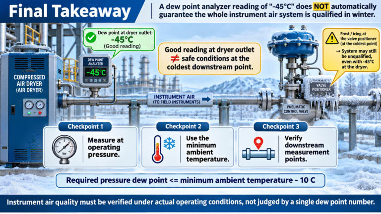
Does a dew point reading of −45°C prove that an instrument air system is qualified?
No. A single dew point reading cannot guarantee the air quality of the entire instrument air network.
Engineers must verify three critical factors:
- Is the dew point measured at the actual operating pressure?
- Is the requirement based on the lowest expected ambient temperature?
- Does the measurement represent the actual conditions at downstream instrument connections?
The most important principle is simple:
Instrument air quality must be evaluated under actual operating conditions, not judged by a single number displayed on an analyzer.
A dew point reading that looks excellent at the dryer outlet may not tell the whole story at the coldest point of the pipeline.
In winter, the weakest point in the instrument air system may be far away from the dryer.
And that is exactly where the trouble begins.