Characteristics: The Slip-On Flange is a type of flange connected to a vessel or pipeline using a fillet weld, also known as a lap joint flange. The connection between the Slip-On Flange and the pipe is achieved by first inserting the pipe into the flange bore to the appropriate position and then performing a fillet weld. Its advantages include easier alignment during welding assembly and lower cost, which has led to its widespread use. The Slip-On Flange can be further subdivided into two types: Neck Slip-On Flange and Plate Slip-On Flange.
Applications: It is suitable for piping systems with relatively low pressure levels where pressure fluctuations, vibrations, and shocks are not severe. It is widely used in medium and low-pressure pipeline connections.
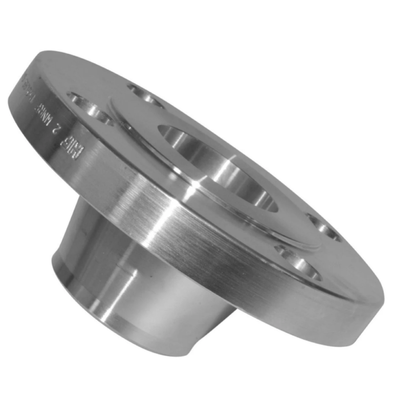
2. Neck Slip-On Flange
Characteristics: The Neck Slip-On Flange features a short neck, which is designed to enhance the strength of the flange and improve its load-bearing capacity, making it suitable for use in higher-pressure pipelines.
Applications: It has a wide range of diameters and is suitable for various piping systems. Additionally, its nominal pressure range is extensive, allowing it to meet the requirements of different pressure levels. It is widely used in pipeline systems across industries such as petroleum, chemical, natural gas, metallurgy, food, and pharmaceuticals.
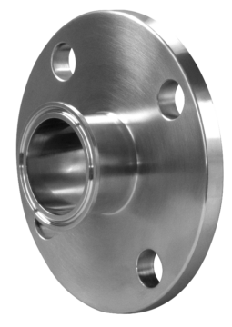
3. Weld Neck Flange
Characteristics: Also known as a High Neck Flange, the Weld Neck Flange differs from other flanges due to its long, tapered neck that extends from the welding point to the flange body. The neck’s wall thickness gradually transitions to match the pipe wall thickness along its height, which improves the stress distribution and increases the flange’s strength. Weld Neck Flanges are primarily used in demanding conditions. Although they are large, heavy, and expensive, their structure is reasonable, providing high strength and rigidity. They can withstand high temperatures, high pressures, repeated bending, and temperature fluctuations.
Applications: Due to its excellent performance, the Weld Neck Flange is widely used in large vessels in industries such as aerospace, petroleum, and chemical processing. It is especially suitable for pipelines with significant pressure or temperature fluctuations, as well as for high-temperature, high-pressure, or low-temperature pipelines. It is also used in pipelines transporting expensive, flammable, explosive, or toxic gases.
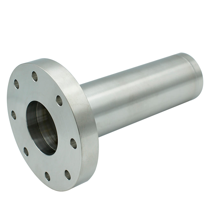
4. Socket Weld Flange
Characteristics: The basic shape of the Socket Weld Flange is similar to that of the Neck Slip-On Flange, but it has a socket in the flange bore where the pipe is inserted and then welded. A weld bead is applied around the flange’s backside. The fatigue strength of a Socket Weld Flange, when welded on both the inner and outer sides, is 50% greater than that of a Slip-On Flange. When using this flange, the internal diameter must match the internal diameter of the pipe. Socket Weld Flanges are only suitable for pipelines with a nominal diameter of DN80 or smaller.
Applications: The Socket Weld Flange has minimal welding deformation and offers good sealing performance. It can be used in situations where the pressure ranges from 1.0 to 10.0 MPa and is widely used in industries such as boiler pressure vessels, petroleum, and chemical processing.
5. Threaded Flange
Characteristics: The Threaded Flange has an internal bore that is machined with pipe threads, allowing it to connect with threaded pipes without the need for welding, making it a non-welded flange. Compared to welded flanges, the Threaded Flange offers the advantage of easy installation and maintenance.
Applications: It is suitable for pipelines where welding is not permitted, such as those used in fire protection systems, gas lines, and industrial and residential water supply lines for hot and cold water. However, it is not recommended to use Threaded Flanges in conditions where the temperature fluctuates sharply or where the temperature exceeds 260°C or drops below -45°C, to avoid the risk of leakage.
6. Integral Flange
Characteristics: The Integral Flange refers to the flange located at the inlet or outlet of pumps, valves, and other mechanical equipment, specifically designed for connection with flanges on pipes. These flanges are usually cast as part of the equipment.
Applications: It is typically integrated with the mechanical equipment, serving as an essential part of the device.
7. Blind Flange
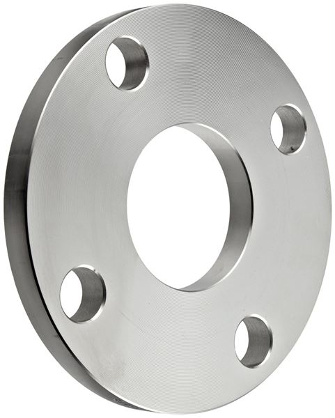
Characteristics: The Blind Flange has no central hole and is used to completely seal off the end of a pipeline.
Applications: It is used to isolate and block pipelines for equipment maintenance, cleaning, replacement, or other upkeep tasks. The Blind Flange can be easily removed, making it convenient for maintenance work.
8. Lap Joint Flange
Characteristics: The Lap Joint Flange can rotate, making it easier to align the bolt holes during installation. When using this type of flange connection, the flange attachment’s material matches the pipe material, while the flange itself can be made from a different material.
Applications: It is commonly used in large-diameter pipelines where precise alignment of bolt holes is necessary. The Lap Joint Flange is particularly suitable for pipelines carrying corrosive media and non-ferrous metal piping systems, helping to minimize the use of expensive materials.
II. Main Technical Parameters of Flanges
1. Nominal Diameter (DN)
Definition: Nominal Diameter (DN) is the standard diameter of a flange used to represent the size of the flange’s connection to a pipe or equipment. It is typically expressed as DN (Nominal Diameter), with the unit in millimeters (mm). This parameter is a crucial reference when selecting a flange.
2. Nominal Pressure
Definition: Nominal Pressure (PN) is the standard pressure rating of a flange, representing the maximum allowable operating pressure for the flange at a specified temperature. It is typically expressed as PN (Nominal Pressure) in units of megapascals (MPa) or bar. This parameter is essential for determining the appropriate flange for a given pressure condition in piping systems.
3. Flange material
Material Types: Flanges can be manufactured from a variety of materials, with common options including carbon steel, stainless steel, and alloy steel. Each material has distinct physical and chemical properties, making it suitable for different working environments and conditions. The choice of material directly impacts the flange’s strength, corrosion resistance, wear resistance, as well as the manufacturing cost and service life of the flange.
4. Sealing Surface Types
Definition: The sealing surface type refers to the design and shape of the contact surface on the flange that ensures a proper seal when joined with another flange or a sealing element. The choice of sealing surface type affects the sealing performance and suitability for different applications.
Common Types:
Flat Face (FF): The entire surface of the flange is flat, providing a wide contact area. It is typically used for low-pressure applications where the risk of gasket blowout is minimal.
Raised Face (RF): The sealing surface is slightly raised above the flange’s face. This type is widely used in medium to high-pressure applications, as it concentrates the gasket load and improves sealing efficiency.
Ring Type Joint (RTJ): The flange features a groove for a metal ring gasket, creating a high-pressure, leak-proof seal. It is commonly used in high-pressure and high-temperature environments, such as in the oil and gas industry.
Tongue and Groove (T&G): One flange has a protruding tongue, while the mating flange has a matching groove. This type ensures proper alignment and is often used in applications requiring a reliable seal with minimal leakage.
Male and Female (M&F): Similar to T&G, but with a slightly different design. One flange has a raised male surface, and the other has a recessed female surface. This type is used to ensure proper gasket placement and alignment.
The choice of sealing surface type is critical to achieving the desired sealing performance in specific applications.
5. Flange Manufacturing Standards
Definition: Flange manufacturing standards are established guidelines and specifications that dictate the design, dimensions, materials, testing, and performance requirements for flanges. These standards ensure compatibility, safety, and quality across different industries and applications.
Common Flange Manufacturing Standards:
ASME/ANSI (American Society of Mechanical Engineers/American National Standards Institute): Widely used in the United States and internationally, ASME/ANSI standards, such as ASME B16.5, cover pipe flanges and flanged fittings, specifying dimensions, pressure ratings, and material requirements.
DIN (Deutsches Institut für Normung): These German standards are commonly used in Europe and other regions. DIN standards, such as DIN 2501, provide specifications for flanges, including dimensions, pressure classes, and material grades.
EN (European Norms): EN standards, such as EN 1092-1, are European standards that cover flanges and their specifications for various applications, ensuring consistency across the European Union.
JIS (Japanese Industrial Standards): These standards, like JIS B2220, are prevalent in Japan and Asia, detailing flange dimensions, pressure ratings, and material specifications for various applications.
GB (Guobiao Standards): China’s national standards, such as GB/T 9112, govern the manufacturing and testing of flanges in the Chinese market, covering a wide range of flange types and materials.
API (American Petroleum Institute): API standards, such as API 6A, are specifically designed for the oil and gas industry, detailing requirements for flanges used in drilling and production operations, with a focus on high pressure and harsh environments.
Applications: Adherence to these standards is crucial for ensuring that flanges meet the necessary safety and performance requirements in their respective applications. It also ensures that flanges from different manufacturers are interchangeable and compatible with other components within a piping system.