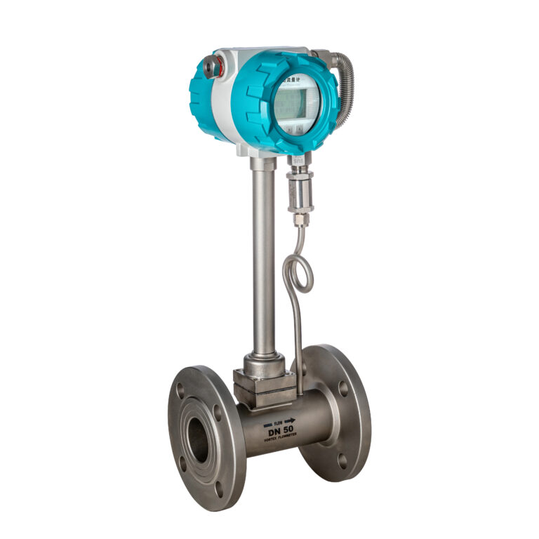
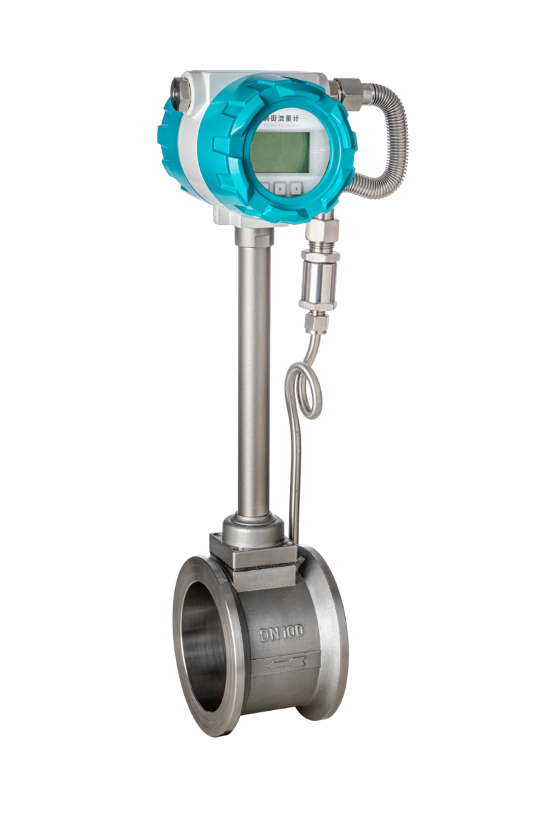
Vortex flow meters are widely used across industrial automation due to their simple structure, wide turndown ratio, and strong adaptability. They are commonly deployed for measuring liquids, gases, and steam.
However, in real operating environments, vortex meters may occasionally suffer from pulse loss — a condition where part of the vortex shedding signals generated by the fluid are not successfully detected or converted into electrical pulses.
This issue leads to flow readings lower than the actual value, which directly affects production accounting and energy management.
This article provides a comprehensive engineering analysis of the causes, symptoms, and corrective actions for pulse loss, based on measurement principles and field experience.
1. What Is Pulse Loss and Why Does It Matter?
Pulse loss refers to the failure of the sensor to fully detect the vortex shedding frequency generated by the bluff body.
In other words, some vortices are formed in the fluid, but the transmitter does not recognize them, resulting in a reduced pulse output.
Key risks include:
1. Incorrect measurement
In steam distribution systems, pulse loss leads to mismatch between main meters and sub-meters, often causing “negative line loss,” creating disputes or incorrect energy billing.
2. Misleading operational decisions
Example: A boiler producing 5 tons of steam per ton of coal may appear to produce only 4 tons due to pulse loss, resulting in inaccurate efficiency calculations.
3. Instrumentation malfunction
In severe cases, pulse output may drop to zero, making the meter unable to reflect the actual process flow, potentially affecting downstream control systems.
Pulse loss is therefore an issue that cannot be ignored in steam and gas metering applications.
2. Fundamental Causes of Pulse Loss
Pulse loss is typically the combined effect of unstable vortex formation and ineffective signal detection.
The main causes fall under three categories.
A. Fluid-Related Causes
1. Two-phase flow (most common in steam applications)
When wet steam or condensate water enters the pipeline, large droplets strike the bluff body and disturb vortex formation.
Wet steam turbulence weakens vortex strength and makes signal detection unstable.
Typical scenario:
A plant reopened steam lines after maintenance; a leaking valve allowed cold water into the line, causing the vortex meter to show extremely low values — a direct result of pulse loss.
2. Low flow velocity / low Reynolds number
Vortex shedding requires a sufficiently high Reynolds number (generally Re > 20,000).
When flow velocity is too low, vortices form irregularly or too weakly for detection.
3. Fluid impurities or viscosity issues
Particles or sticky fluids can reduce vortex strength or cause noise signals that mask the true vortex frequency.
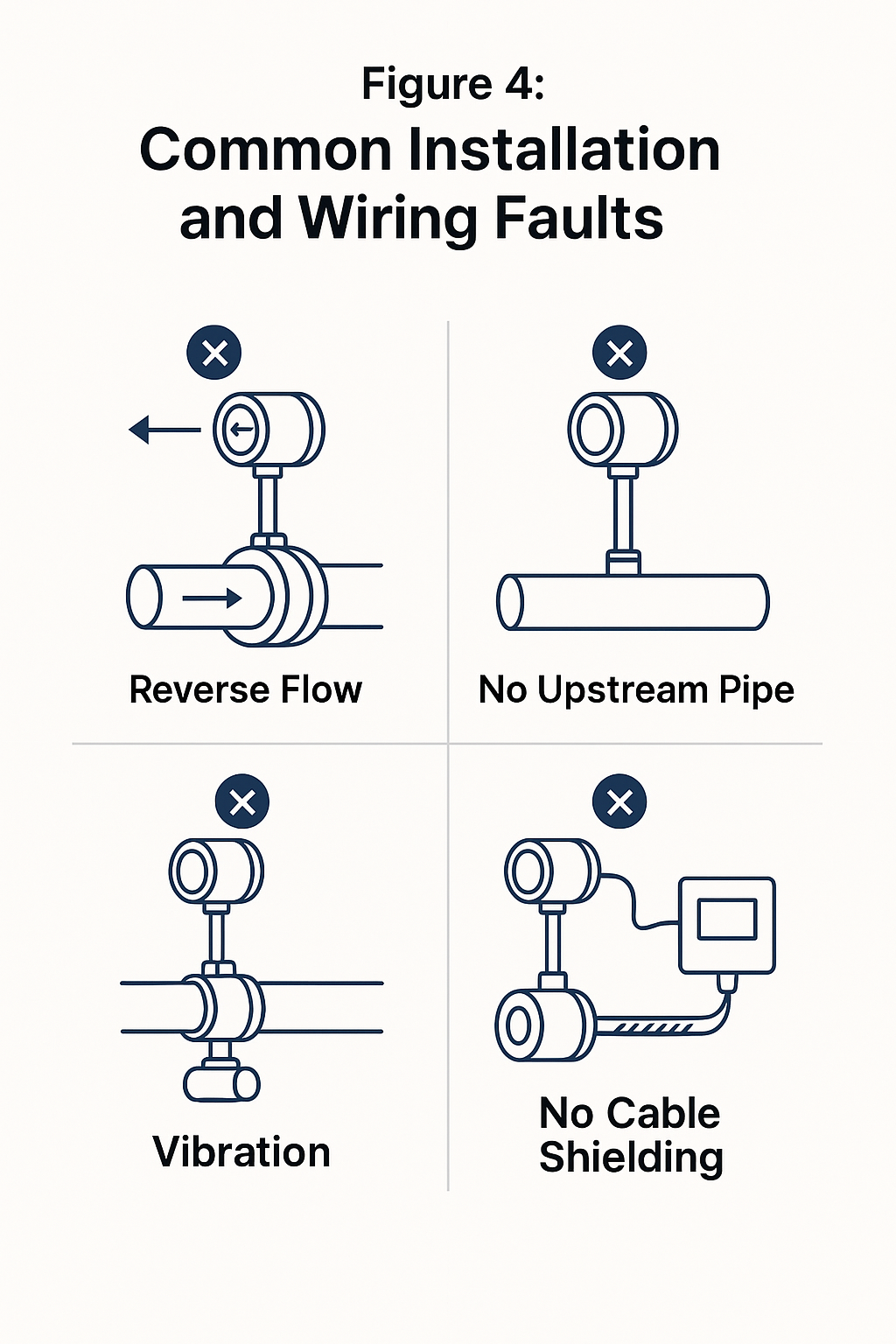
B. Installation and Environmental Factors
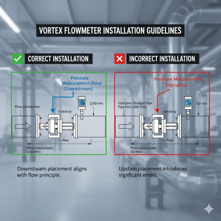
1. Insufficient straight pipe length
Upstream elbows, valves, reducers, or obstructions create turbulence that inhibits stable vortex formation.
Recommended pipe requirements:
Upstream ≥ 10D
Downstream ≥ 5D
2. Pipeline vibration
External vibration from pumps, compressors, or valves can couple into the sensor, causing false triggering or missed pulses.
3. Electromagnetic interference (EMI)
Inverter-driven motors, high-power cables, welding equipment, and grounding issues may distort the pulse signal.
4. Condensation issues in steam lines
When condensate accumulates due to missing or faulty steam traps, the meter continuously works under two-phase flow, making pulse loss unavoidable.
C. Instrument-Related Causes
1. Low detection sensitivity
Older or low-quality sensors may struggle to detect weak vortex signals, especially at low flows.
2. Outdated signal processing algorithms
If noise filtering thresholds are set poorly, the instrument may incorrectly reject valid pulses.
3. Sensor aging or mechanical wear
Long-term vibration or high-temperature operation may degrade sensor performance.
3. Practical Solutions to Prevent and Correct Pulse Loss
Pulse loss can almost always be resolved by optimizing fluid conditions, installation, and instrument parameters.
A. Improve Fluid Conditions
1. Eliminate two-phase flow
Install steam traps upstream and downstream of the meter
Drain condensate regularly
Inspect valve sealing to prevent water ingress
Ensure the measuring section remains fully dry steam
2. Keep the working flow within vortex meter range
Ensure the flow rate is above the minimum measurable velocity
Avoid oversized meters in low-flow applications (incorrect sizing is a frequent hidden cause)
3. Maintain clean pipelines
Remove particles
Prevent deposition on the bluff body
Conduct regular maintenance
B. Ensure Proper Installation and Signal Quality
1. Confirm adequate straight pipe runs
For problematic pipe layouts, consider using:
Flow conditioners
Longer installation sections
Relocating the meter away from turbulence sources
2. Reduce vibration impact
Add vibration damping brackets
Avoid installing meters near rotating machinery
3. Improve electrical and EMI protection
Use shielded cables
Ensure proper single-point grounding
Route signal cables away from high-power lines
C. Upgrade Instrument Hardware or Configuration
1. Use a higher-sensitivity sensor technology
Example: upgrading from piezoelectric to capacitive sensors improves weak signal detection.
2. Update firmware and algorithms
Advanced algorithms distinguish vortex frequencies more accurately and reduce false noise rejection.
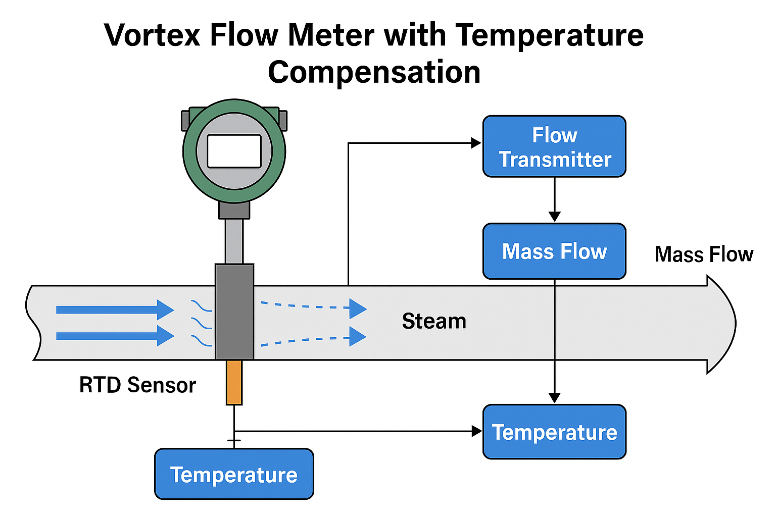
3. Apply steam dryness or humidity compensation
In steam measurement, if the dryness fraction is known, the transmitter can compensate for lost pulses.
4. Field Case Study
A district heating company attempted to reduce heat loss by closing 31 steam traps along a distribution line.
As a result:
Large amounts of condensate accumulated in the downstream pipeline
The vortex meter showed unstable values between 0 and 0.75 t/h, while the actual steam flow was about 2.5 t/h
When the steam trap near the user station was reopened, condensate was discharged, and the vortex meter immediately returned to normal readings.
Conclusion:
Proper condensate removal is one of the most critical steps in preventing pulse loss in steam measurement.
5. Conclusion
Pulse loss in vortex flow meters occurs when the meter fails to properly detect vortex shedding due to fluid conditions, installation issues, or signal processing limitations.
Addressing the problem requires a combined approach:
Ensure single-phase, stable fluid flow
Maintain a stable flow field through proper installation
Use high-quality sensors and optimized algorithms
Perform regular inspection and maintenance
By applying these engineering measures, industries can significantly improve the accuracy and reliability of vortex flow measurement — especially in steam applications where precise energy accounting is essential.