Ultrasonic Level Measurement Problems? 80% Are Caused by One Ignored Parameter: Beam Angle - Just Measure it

Ultrasonic Level Measurement Problems? 80% Are Caused by One Ignored Parameter: Beam Angle

Ultrasonic level transmitters are widely used in water treatment, chemical processing, and storage tanks due to their non-contact measurement and easy installation.

However, many engineers encounter the same frustrating issues:

  • Unstable readings
  • False echoes
  • Signal loss
  • Measurement failure

๐Ÿ‘‰ The truth is:
In over 80% of cases, the root cause is NOT the instrument โ€” but an overlooked parameter: beam angle.

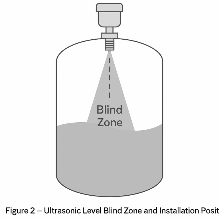
What Is Ultrasonic Beam Angle?

The beam angle defines how ultrasonic waves spread after being emitted from the sensor.

Technically, it is defined as:
๐Ÿ‘‰ The angle where sound pressure drops to -6 dB (half power point) from the central axis.

In simple terms:

  • Ultrasonic waves are not straight lines
  • They spread like a cone (similar to a flashlight beam)
  • Everything inside this cone can reflect signals back

๐Ÿ“Œ Example:
A sensor with a 10ยฐ beam angle will cover a diameter of ~1.75 m at 10 m distance.

๐Ÿ‘‰ That means:
ANY object in this range can interfere with measurement.

Why Beam Angle Matters More Than You Think

Most measurement failures happen because the beam hits unintended objects:

  • Tank walls
  • Pipes
  • Ladders
  • Agitators
  • Foam / turbulence

๐Ÿ‘‰ When reflected signals from these objects are stronger than the liquid surface echo, the sensor gives wrong readings.

Real Case โ€“ Why Measurement Fails

A real example:

  • Tank height: 5 m
  • Beam angle: 15ยฐ
  • Distance to wall: 0.3 m

Calculation shows the beam fully hits the tank wall.

๐Ÿ‘‰ Result:

  • Continuous false echoes
  • Completely unreliable measurement

Conclusion: Even correct installation cannot fix wrong beam angle selection.

What Determines Beam Angle?

Two key factors:

1. Transducer Size (D)

  • Larger diameter โ†’ smaller beam angle โ†’ better focus

2. Frequency (f)

  • Higher frequency โ†’ smaller beam angle
  • BUT โ†’ higher attenuation โ†’ shorter measuring range

๐Ÿ‘‰ Trade-off:

  • Small beam angle = better accuracy
  • Large beam angle = longer range but more interference

Selection Rule (Critical for Real Projects)

Before choosing a model, you MUST calculate:

๐Ÿ‘‰ Beam radius at max distance:

R = H ร— tan(ฮธ/2)

Where:

  • H = measuring distance
  • ฮธ = beam angle

โœ” Installation requirement:
๐Ÿ‘‰ Distance to any obstacle must be greater than R + 20% safety margin

How We Solve This in Real Projects

In many projects, unstable measurement is not solved by replacing instruments โ€” but by correct beam angle selection and installation optimization.

We typically help clients:

  • Calculate beam coverage based on tank size
  • Recommend suitable frequency & sensor size
  • Avoid nozzle and wall interference
  • Optimize installation position

๐Ÿ‘‰ This approach solves most issues without trial-and-error replacement

5 Common Mistakes to Avoid

  1. Choosing based only on range, ignoring beam angle
  2. Assuming all manufacturers use the same beam angle standard
  3. Relying on software filtering to fix physical interference
  4. Blindly choosing higher frequency sensors
  5. Ignoring side lobe reflections

๐Ÿ‘‰ These mistakes lead to most field failures.

Key Takeaway

Ultrasonic level measurement reliability is NOT determined by a single parameter.

๐Ÿ‘‰ But beam angle is the core factor that connects:

  • Selection
  • Installation
  • Performance
  • Troubleshooting

Need Help Selecting the Right Model?

If you are experiencing:

  • Unstable readings
  • Echo loss
  • Difficult tank conditions
  • Unsure about beam angle selection

๐Ÿ‘‰ We can help you select the right model based on your application.

๐Ÿ“Œ Just provide:

  • Tank size
  • Medium
  • Installation conditions

We will recommend the most suitable solution.

Share This Story, Choose Your Platform!

Contact Us

    Please prove you are human by selecting the house.
    Translate ยป