
When engineers see a combustible gas or toxic gas detector on an instrumentation drawing, one question often comes up:
Should the gas detector signal go to the DCS or the SIS?
Because gas detection is safety-related, it may seem natural to assume that every gas detector should be connected directly to the Safety Instrumented System (SIS).
In practice, however, the answer is not that simple.
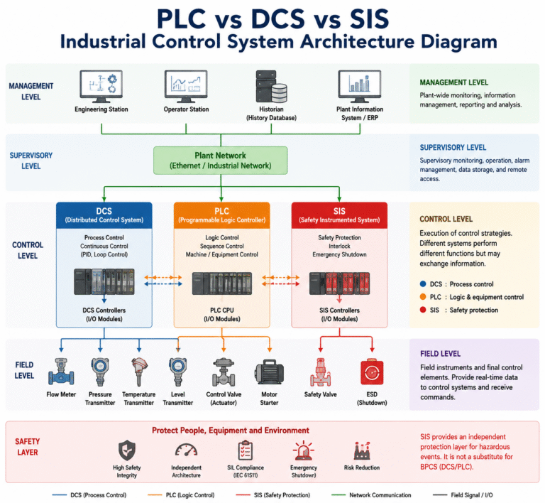
In some petrochemical facilities, combustible and toxic gas detectors are connected to a dedicated Gas Detection System (GDS), with alarm and status information transferred to the Distributed Control System (DCS).
In other applications, selected gas detectors that initiate shutdown actions are connected independently to the SIS.
There are also installations where gas detector signals are brought into the DCS for centralized monitoring and alarm handling.
All of these arrangements may appear capable of achieving the same basic objective—detecting gas and generating an alarm—but they do not necessarily perform the same safety function.
The key question is therefore not simply:
“Where should the gas detector signal be connected?”
A better question is:
“What function is this gas detector required to perform?”
In simple terms:
GDS detects and alarms.
DCS informs the operator.
SIS performs an independent safety action when gas detection is part of a safety function.
The original design principle is also reflected in GB/T 50493-2019, which treats combustible and toxic gas detection and alarm as a dedicated function rather than ordinary process monitoring.

1. First Understand the Roles of GDS, DCS, and SIS
Before deciding where a gas detector signal should go, it is important to understand the different responsibilities of the three systems.
GDS — Gas Detection System
The primary purpose of a GDS is to:
- continuously monitor combustible or toxic gas concentrations;
- generate gas alarms;
- monitor detector faults;
- provide local or centralized warning;
- supervise detector maintenance or bypass conditions.
Gas detection is fundamentally different from normal process measurement.
Pressure, temperature, flow, and level measurements usually tell us what is happening inside the process.
Gas detectors often tell us what is happening after process containment has been lost.
That distinction is extremely important.
For example, suppose a hydrocarbon pump develops a mechanical seal leak.
The pump may continue operating normally. Its discharge pressure and flow rate may remain almost unchanged.
From the DCS process data, everything may still look normal.
However, a combustible gas detector installed near the pump may already detect an increasing gas concentration.
This is why gas detection should not simply be treated as another ordinary process measurement. The source article accordingly emphasizes that the gas detection and alarm system should independently perform detection, alarm, and fault monitoring.
2. What Is the Role of the DCS?
Although gas detection should be handled by the appropriate gas detection system, operators still need to see what is happening in the plant.
For this reason, GDS information is commonly transferred to the DCS.
Typical information may include:
- real-time gas concentration;
- first-level alarm;
- second-level alarm;
- detector fault;
- maintenance status;
- bypass or inhibit status.
This allows operators to view gas detection information together with process conditions on the same operating interface.
The DCS can then provide:
centralized display, alarm presentation, trending, and historical recording.
This is convenient and operationally useful.
But there is an important distinction:
Displaying a gas detector signal in the DCS does not necessarily mean that the DCS performs the gas detection and safety function.
A typical arrangement is therefore:
Gas Detector → GDS → DCS
The GDS performs the gas detection and alarm functions, while the DCS provides centralized operator monitoring.
3. First-Level and Second-Level Gas Alarms
Another common source of confusion is the relationship between gas alarm levels and shutdown functions.
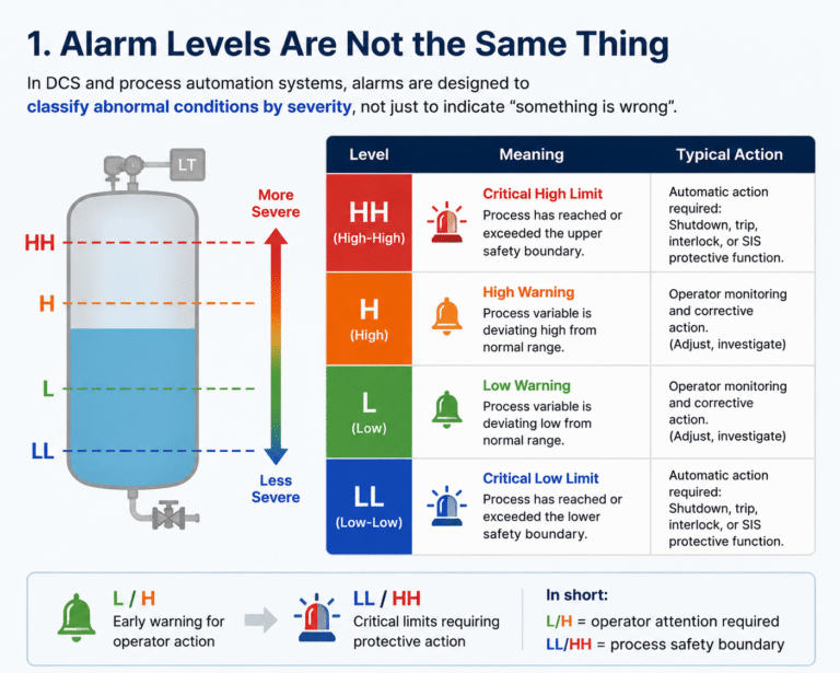
According to the source article’s discussion of GB/T 50493-2019, combustible gas detection commonly uses multiple alarm levels. It states that the first alarm setting should not exceed 25% LEL, while the second alarm setting should not exceed 50% LEL.
For example, a combustible gas detector installed in a pump area might be configured conceptually as:
First-level alarm:
Gas concentration reaches the first alarm threshold → notify the control room and field personnel.
Second-level alarm:
Gas concentration reaches the higher alarm threshold → activate additional audible/visual alarms and require further operator response.
At this stage, both signals can still be part of the normal gas detection and alarm function.
This leads to an important engineering point.
4. Does a High-High Gas Alarm Automatically Mean ESD?
No.
Seeing a tag such as:
Gas Detector HH
on a drawing does not automatically mean:
ESD Trip
A second-level or high-high gas alarm first indicates that the gas concentration has reached a defined alarm threshold.
Whether that condition should also:
- stop a pump;
- trip a compressor;
- close an emergency shutdown valve;
- isolate a process section;
- stop ventilation;
- initiate emergency ventilation; or
- initiate a wider ESD action
is a separate design decision.
For example, consider the same gas concentration in three different locations:
Outdoor pump area:
Natural ventilation may allow released gas to disperse relatively quickly.
Enclosed compressor building:
A release may accumulate much faster.
Analyzer shelter:
The confined space may create different personnel exposure and ignition risks.
The gas concentration may be identical, but the required protective actions may be completely different.
Therefore:
An alarm threshold determines when an alarm is generated. A shutdown philosophy determines what automatic action, if any, should follow.
The two should not be confused.
5. When Should a Gas Detector Signal Enter the SIS?
The relationship with the SIS becomes much more important when gas detection is used to initiate an automatic protective action.
Consider an enclosed compressor building with several combustible gas detectors.
Suppose the safety philosophy requires that when two detectors reach a specified concentration, the system automatically:
- trips the compressor; and
- closes the emergency shutdown valve at the compressor inlet.
The functional chain is now:
Gas Detection → Logic Decision → Shutdown / Isolation
This is no longer merely an operator alarm.
The original article notes that where combustible or toxic gas detection signals are used as inputs to a safety instrumented system, the detectors should be independently arranged and their outputs sent to the corresponding safety instrumented system.
A simplified architecture may therefore look like this:
Gas Detector → SIS Logic Solver → ESD Valve / Equipment Trip
However, one additional distinction is important:
An automatic shutdown action should not automatically be assumed to be a Safety Instrumented Function (SIF).
Whether the function is formally treated as a SIF depends on the project’s hazard and risk assessment and the allocation of safety functions.

6. Gas Detection as a Safety Instrumented Function
If a hazard assessment determines that gas detection followed by automatic shutdown is required as an independent risk-reduction function, the design must be considered in the context of the safety lifecycle.
This may involve:
HAZOP → LOPA / Risk Assessment → SIF Definition → SIL Requirement → Detailed Design → Testing and Maintenance
Once gas detection becomes part of a SIF, engineers must consider much more than simply connecting a detector to an SIS input card.
The complete function may include:
Sensor
One or more combustible or toxic gas detectors.
Logic Solver
The SIS performs the required voting and shutdown logic.
Final Element
This may include:
- emergency shutdown valves;
- isolation valves;
- compressor trips;
- pump trips; or
- other protective actions.
The design must also consider detector configuration, voting logic, final-element reliability, proof testing, bypass management, and other safety lifecycle requirements.
The source article specifically connects this stage with HAZOP/LOPA, SIL, sensor configuration, voting, final elements, periodic testing, and bypass management.
7. Why Use 1oo2, 2oo3, or Other Voting Logic?
Gas detection shutdown systems frequently use voting arrangements such as:
- 1oo2;
- 2oo3;
- 2ooN.
Why?
Because gas detectors operate under very different conditions from many conventional process transmitters.
A pressure transmitter measures pressure through a defined process connection.
A gas detector must detect gas that has:
- escaped from the process;
- dispersed through the surrounding environment; and
- physically reached the sensing element.
Its response can therefore be affected by many factors, including:
- sensor contamination;
- sensor aging;
- calibration drift;
- environmental conditions;
- interfering substances;
- airflow;
- ventilation; and
- detector location.
If one gas detector reaching a high alarm immediately shuts down an entire process unit, nuisance trips may become unacceptable.
Voting logic can reduce the probability of an unnecessary shutdown.
But there is an equally important warning:
Voting should never be made more restrictive simply to reduce nuisance trips.
The resulting configuration must still provide adequate protection against the identified hazardous scenario.
8. A 2oo3 Logic Is Only Useful If the Detectors Can Detect the Same Hazard
This is one of the most important practical issues in gas detection design.
Suppose three combustible gas detectors are configured in a:
2oo3 voting arrangement.
From a logic perspective, the design looks reasonable.
Two of the three detectors must reach the trip condition before the shutdown is initiated.
But now consider their physical installation.
What if all three detectors are installed in locations where a credible gas release is unlikely to reach two detectors simultaneously?
In that case, the voting logic may be perfectly implemented in the SIS, yet the safety function may still fail to respond as intended.
The source article makes exactly this point: for 2oo3 voting, the three detectors need to provide meaningful coverage of the same leakage scenario; otherwise the released gas may never reach two detectors and the interlock may not operate.
This is why:
Gas detector placement and voting philosophy must be evaluated together.
9. Detector Location May Matter as Much as the SIS Logic
A gas detector does not directly measure the process condition inside a pipe or vessel.
It measures the concentration of gas that reaches its sensing location after a release.
Therefore, detector response may depend on:
- potential leak source;
- release direction;
- gas or vapor density;
- wind direction;
- ventilation rate;
- equipment layout;
- obstructions;
- detector elevation; and
- whether the installation is indoors or outdoors.
For example, the installation strategy for natural gas may differ from that for heavier hydrocarbon vapors.
Similarly, detector placement in an enclosed compressor building may be very different from detector placement in an open process area.
Detector location is already important for a conventional GDS alarm.
When the detector also participates in an ESD or safety function, its coverage becomes even more critical.
Three detectors arranged in a 2oo3 configuration may look impressive on the cause-and-effect chart.
But if all three are installed in poor locations, the real question is no longer:
“Is 2oo3 the correct voting logic?”
The real question becomes:
“Will at least two detectors actually detect the hazardous release in time?”
The source article emphasizes this distinction by discussing the effects of leak location, wind, ventilation, obstructions, installation height, and gas density on detection.
10. What Information Should Be Sent from the GDS to the DCS?
In an operating plant, control-room personnel generally need centralized access to gas detection information.
It is therefore common for the GDS to transfer information to the DCS, including:
Gas concentration → DCS display
First-level alarm → DCS alarm
Second-level alarm → DCS alarm
Detector fault → DCS diagnostic indication
Maintenance / bypass status → DCS status indication
This allows operators to monitor both process conditions and gas hazards from a common interface.
The DCS may then provide:
- process overview;
- gas alarm visualization;
- alarm management;
- trends;
- event records; and
- historical data.
The DCS is therefore extremely useful for operator awareness.
But operator visibility should not be confused with execution of an independent safety function. The source article summarizes the practical relationship as GDS for detection/alarm, DCS for operator visibility, and independently arranged detector signals to SIS where automatic safety action is required.
11. Typical GDS–DCS–SIS Signal Architecture
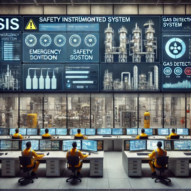
A simplified plant architecture can be understood as follows:
Normal Gas Detection and Alarm
Gas Detector → GDS → Alarm
The GDS performs detection, alarm handling, and detector supervision.
Operator Monitoring
GDS → DCS → Display / Trend / History
The DCS provides centralized visualization and operational information.
Safety Shutdown Function
Independent Gas Detector(s) → SIS → Voting Logic → Final Element
The SIS may initiate actions such as:
Compressor Trip
Pump Trip
ESD Valve Closure
Process Isolation
The exact architecture, including whether information is transferred by hardwired signals or digital communication, depends on project specifications and system design.
12. Can the Same Area Have Detectors for Both GDS and SIS?
Yes.
This is an important point because engineers sometimes assume that every detector in one area must have the same system architecture.
That is not necessarily the case.
An area may have one group of gas detectors dedicated to normal gas detection and alarm:
Detector → GDS → DCS
At the same time, separately arranged detectors may participate in an automatic shutdown function:
Detector → SIS → ESD
The two groups may be detecting the same type of gas, but their functional purposes are different.
The source article explicitly notes that the same area can contain detectors serving these different purposes.
13. Three Questions to Decide Where a Gas Detector Signal Should Go
When reviewing a P&ID, cause-and-effect chart, instrument index, or control system architecture, three questions can usually clarify the signal destination.
Question 1: Is the detector only required to generate an alarm?
If yes, the primary function belongs to the gas detection and alarm system.
Question 2: Does the operator need to see the gas concentration, alarm, or detector status?
If yes, the relevant information should normally be made available to the DCS or operator interface.
Question 3: Is the gas detection signal used in an automatic safety action identified by the project’s risk assessment?
If yes, the signal path and function must be evaluated according to the applicable SIS/SIF requirements.
This is essentially the three-question decision method given in the original article.

Conclusion
So, should a gas detector signal go to the GDS, DCS, or SIS?
There is no single answer based only on the fact that the instrument is a gas detector.
The correct destination depends on the function assigned to the signal.
For normal gas detection and alarm, the GDS performs the primary detection and alarm function.
For operator monitoring, alarm presentation, trending, and historical records, relevant information can be transferred to the DCS.
When gas detection is used to initiate an automatic shutdown or isolation function that has been allocated as part of the plant’s safety instrumented protection, the appropriate detector signals and logic must be incorporated into the SIS architecture.
Most importantly, when gas detectors participate in a safety function, engineers should not focus only on SIL, voting logic, or the logic solver.
A perfectly programmed 2oo3 voting scheme provides little protection if the detectors are poorly positioned and the hazardous gas release cannot reach two of them.
That leads to the most useful way to remember the entire subject:
GDS detects and alarms. DCS informs the operator. SIS acts when gas detection is part of an independent safety function.
And before deciding where any gas detector signal should go, ask three questions:
Is it only for alarm?
Does the operator need to see it?
Is it part of a risk-assessed safety function?
Once those three questions are answered, the GDS–DCS–SIS architecture usually becomes much easier to define.