
Orifice plate flowmeters are widely used in industrial applications to measure the flow of liquids, gases, and steam. Their relatively simple construction, established measurement principles, and compatibility with differential pressure (DP) transmitters make them a common choice in process plants.
However, one of the most frequently overlooked causes of measurement errors is impulse line blockage.
When an orifice flowmeter displays an unexpectedly high or low flow rate, operators may immediately suspect a faulty differential pressure transmitter or an incorrectly sized orifice plate. In reality, the problem may be caused by a partially or completely blocked impulse line.
A common troubleshooting rule suggests:
- High-pressure impulse line blocked → Flow reading decreases.
- Low-pressure impulse line blocked → Flow reading increases.
- Both impulse lines blocked → Flow reading remains constant.
Although these outcomes can occur under certain conditions, they are not universal rules.
The actual measurement error depends on how the process pressures change after the blockage occurs.
Understanding this distinction is essential for accurate troubleshooting.
1. How Does an Orifice Flowmeter Measure Flow?
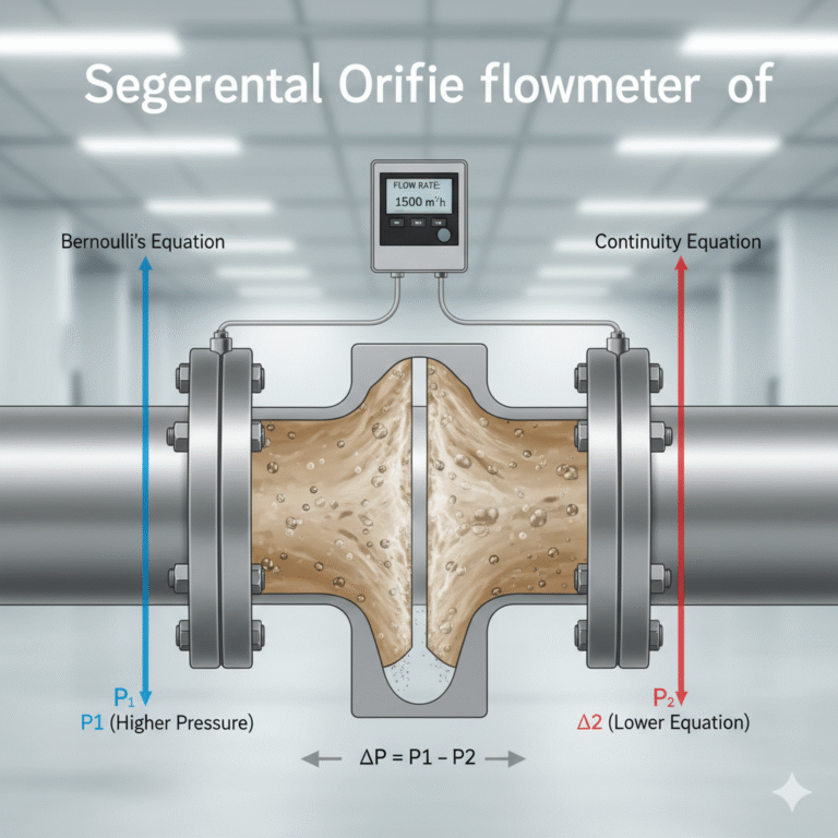
An orifice flowmeter operates according to the differential pressure principle.
When fluid passes through the restriction created by an orifice plate, its velocity increases and its static pressure decreases. The resulting pressure difference is measured by a differential pressure transmitter.
The basic relationship is:
ΔP = P_H − P_L
Where:
- ΔP = Differential pressure
- P_H = High-pressure-side pressure
- P_L = Low-pressure-side pressure
For a given orifice installation under constant fluid properties and applicable flow conditions, volumetric flow is approximately proportional to the square root of differential pressure:
Q ∝ √ΔP
This relationship leads to an important principle:
A higher measured differential pressure generally produces a higher calculated flow rate, while a lower measured differential pressure produces a lower calculated flow rate.
For gas and steam applications, density compensation may also be required to obtain accurate mass flow or standardized volumetric flow.
The differential pressure transmitter receives process pressure through two impulse lines connected to the upstream and downstream pressure taps.
If either impulse line becomes restricted or blocked, the pressure reaching the transmitter may no longer accurately represent the actual process conditions.
2. What Happens When the High-Pressure Impulse Line Is Blocked?
The high-pressure impulse line connects the upstream pressure tap to the high-pressure port of the DP transmitter.
Under normal conditions, changes in upstream pressure are transmitted to the transmitter.
When this impulse line becomes completely blocked, the pressure trapped on the transmitter side may remain near its previous value rather than following actual upstream pressure changes.
The resulting measurement error depends on the direction of the pressure change.
Scenario A: Actual Upstream Pressure Increases
Consider the following initial operating conditions:
| Parameter | Initial value |
|---|---|
| Upstream pressure | 500 kPa |
| Downstream pressure | 480 kPa |
| Differential pressure | 20 kPa |
Suppose the high-pressure impulse line becomes blocked while the upstream pressure subsequently increases to 510 kPa.
The downstream pressure remains at 480 kPa.
The actual differential pressure becomes:
ΔP_actual = 510 − 480 = 30 kPa
However, if the pressure trapped in the high-pressure impulse line remains at 500 kPa, the transmitter measures:
ΔP_measured = 500 − 480 = 20 kPa
The transmitter therefore measures a differential pressure lower than the actual value.
Result: The indicated flow rate is lower than the actual flow rate.
Scenario B: Actual Upstream Pressure Decreases
Now suppose the upstream pressure decreases from 500 kPa to 490 kPa while the downstream pressure remains at 480 kPa.
The actual differential pressure becomes:
ΔP_actual = 490 − 480 = 10 kPa
However, the blocked high-pressure line still transmits approximately 500 kPa to the transmitter.
Therefore:
ΔP_measured = 500 − 480 = 20 kPa
The measured differential pressure is now greater than the actual differential pressure.
Result: The indicated flow rate is higher than the actual flow rate.
These examples demonstrate that high-pressure-side blockage does not always cause an under-reading.
The measurement error depends on the relationship between the trapped pressure and the actual upstream pressure.
3. What Happens When the Low-Pressure Impulse Line Is Blocked?
The low-pressure impulse line connects the downstream pressure tap to the low-pressure port of the DP transmitter.
When this line becomes blocked, the pressure on the transmitter side may no longer respond to changes in downstream pressure.
Again, two different outcomes are possible.
Scenario A: Actual Downstream Pressure Decreases
Assume the initial conditions are:
- Upstream pressure: 500 kPa
- Downstream pressure: 480 kPa
- Differential pressure: 20 kPa
The low-pressure impulse line becomes blocked, trapping approximately 480 kPa at the transmitter.
If the actual downstream pressure decreases to 470 kPa, the true differential pressure becomes:
ΔP_actual = 500 − 470 = 30 kPa
However, the transmitter continues to calculate:
ΔP_measured = 500 − 480 = 20 kPa
Result: The indicated flow rate is lower than the actual flow rate.
Scenario B: Actual Downstream Pressure Increases
Now suppose the actual downstream pressure increases to 490 kPa.
The actual differential pressure becomes:
ΔP_actual = 500 − 490 = 10 kPa
However, the transmitter continues to use the trapped low-side pressure of 480 kPa:
ΔP_measured = 500 − 480 = 20 kPa
Result: The indicated flow rate is higher than the actual flow rate.
This explains why low-pressure-side blockage cannot automatically be associated with an excessively high flow indication.
The direction of the error depends on how the downstream pressure changes relative to the trapped pressure.
4. What Happens When Both Impulse Lines Are Blocked?
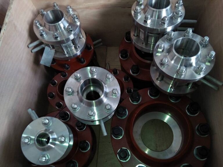
When both the high-pressure and low-pressure impulse lines become completely blocked, the transmitter may be isolated from pressure changes occurring in the process pipeline.
If the trapped pressures remain stable, the differential pressure reading may remain almost unchanged.
For example:
- Trapped high-side pressure: 500 kPa
- Trapped low-side pressure: 480 kPa
- Measured differential pressure: 20 kPa
Even if the actual flow rate changes significantly, the transmitter may continue reporting approximately the same differential pressure.
This can produce a frozen or unresponsive flow indication.
However, the displayed value is not necessarily perfectly constant.
Temperature variations, thermal expansion of trapped fluids, small leaks, and other installation-related effects may cause the measured differential pressure to drift.
A nearly constant flow indication during obvious process changes should therefore be treated as a warning sign, not definitive proof of dual impulse line blockage.
5. Comparison of Impulse Line Blockage Conditions
The following table summarizes the possible effects under the simplified conditions discussed above.
| Blockage condition | Process pressure change | Possible flow indication |
|---|---|---|
| High-pressure side blocked | Actual upstream pressure increases | Too low |
| High-pressure side blocked | Actual upstream pressure decreases | Too high |
| Low-pressure side blocked | Actual downstream pressure decreases | Too low |
| Low-pressure side blocked | Actual downstream pressure increases | Too high |
| Both sides blocked | Actual differential pressure changes | May remain nearly constant |
Important: This table assumes complete blockage, approximately stable trapped pressures, and the other pressure side remaining unchanged. It illustrates the measurement principle rather than predicting every industrial operating condition.
In actual installations, upstream and downstream pressures often change simultaneously. Partial blockage, trapped gas or liquid, and transmitter configuration can also influence the observed behavior.
Consequently, the direction of flow indication error alone cannot reliably identify which impulse line is blocked.
6. Common Causes of Impulse Line Blockage
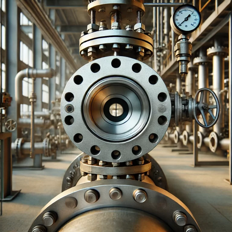
Impulse line blockage can develop gradually or occur suddenly, depending on the process fluid and installation conditions.
6.1 Sediment and Solid Particle Accumulation
In applications involving dirty water, wastewater, slurry, or liquids containing suspended solids, particles may settle inside the impulse lines.
Over time, accumulated material reduces the effective passage diameter and restricts pressure transmission.
6.2 Crystallization and Chemical Deposits
Chemical processes may involve fluids that crystallize or form deposits when temperature, pressure, or concentration changes.
These deposits can gradually restrict pressure taps and impulse tubing.
6.3 Condensate Accumulation in Gas Measurement
In gas applications, condensate may accumulate in improperly routed impulse lines.
This creates additional hydrostatic pressure effects and may restrict the transmission of process pressure.
6.4 Freezing in Cold Environments
Impulse lines containing water or condensate can freeze in low-temperature environments.
Freezing can cause severe restrictions, complete blockage, or even mechanical damage to the tubing.
6.5 Corrosion and Internal Deposits
Corrosion products, scale, and material deterioration may obstruct narrow impulse line passages.
Incorrect material selection or inadequate maintenance can accelerate this process.
7. How to Diagnose a Blocked Impulse Line
Troubleshooting should begin with the behavior of the measurement signal and the corresponding process conditions.
Step 1: Compare Flow Indication with Process Conditions
Review the flowmeter indication alongside relevant operating parameters, such as:
- Pump speed and operating status
- Control valve position
- Upstream and downstream pressures
- Process temperature
- Independent flow or production measurements
If the indicated flow remains unchanged while operating conditions vary significantly, an impulse line problem should be considered.
However, a stable reading alone is not sufficient evidence of blockage.
Step 2: Examine Differential Pressure Trends
Review the raw differential pressure signal rather than relying exclusively on the calculated flow rate.
A partially blocked impulse line may produce:
- Slower pressure response
- Attenuated process pressure fluctuations
- Delayed reaction to flow changes
- Unexpected changes in differential pressure behavior
The precise response depends on which side is restricted, the degree of restriction, and the characteristics of the process.
Step 3: Check the Valve Manifold
Inspect the three-valve or five-valve manifold according to the manufacturer’s operating procedures.
Verify that the isolation and equalizing valves are in their correct normal operating positions.
An incorrectly positioned equalizing valve can significantly affect differential pressure measurement even when the impulse lines are clear.
Step 4: Inspect Impulse Line Conditions
Check for possible causes of blockage, including:
- Sediment accumulation
- Freezing
- Condensation
- Crystallization
- Corrosion products
- Incorrect tubing slope or installation
Where necessary, authorized maintenance personnel should carry out isolation, draining, flushing, or cleaning procedures.
Safety warning: Never loosen an impulse line connection while it is pressurized. High-pressure, high-temperature, toxic, flammable, or corrosive fluids can create serious hazards. Follow the plant’s approved isolation, depressurization, lockout, and maintenance procedures.
Step 5: Verify Transmitter Configuration
Not every incorrect flow indication is caused by an impulse line blockage.
Check the transmitter and control system configuration, including:
- Zero and span settings
- Differential pressure range
- Square-root extraction
- Low-flow cutoff
- Engineering units
- Density compensation, where applicable
Incorrect configuration can produce symptoms that resemble impulse line faults.
8. Can Smart DP Transmitters Detect Impulse Line Blockage?

Modern differential pressure transmitters may incorporate advanced diagnostic functions that help identify impulse line restrictions before they lead to significant measurement errors.
Some diagnostic systems analyze pressure fluctuations and compare them with previously established operating characteristics.
For example, Yokogawa’s EJX transmitter technology offers impulse line blockage detection functions that use fluctuations in differential and static pressure signals.
Depending on the transmitter model and diagnostic configuration, the system may help identify a blockage affecting the high-pressure side, low-pressure side, or both sides.
The underlying principle is that a restricted impulse line changes how process pressure fluctuations are transmitted to the sensing element.
A blockage may therefore be detected through changes in signal fluctuation characteristics even before the average differential pressure reading becomes obviously incorrect.
However, these diagnostic functions have limitations.
Their effectiveness depends on operating conditions, sufficient process pressure fluctuations, proper reference data, and the availability of the relevant transmitter options.
They should complement—not replace—engineering judgment and established maintenance procedures.
9. Preventing Impulse Line Blockage
Preventive maintenance and proper installation can significantly reduce impulse line problems.
Use appropriate impulse line materials. Select tubing and fittings compatible with the process fluid, operating pressure, and temperature.
Maintain correct impulse line routing. Follow the applicable installation recommendations for liquids, gases, and steam to minimize unwanted gas pockets, condensate accumulation, and hydrostatic errors.
Provide freeze protection where required. Insulation, heat tracing, and suitable installation arrangements may be necessary in cold environments.
Consider flushing or purging arrangements. For dirty, crystallizing, or deposit-forming fluids, properly engineered flushing or purging systems may help maintain pressure transmission.
Monitor signal behavior. Periodic review of differential pressure trends and diagnostic alarms can reveal developing problems.
Establish a maintenance schedule. Inspection and cleaning intervals should reflect the process fluid, operating history, and criticality of the measurement point.
10. Common Troubleshooting Mistakes
Several common assumptions can lead to incorrect fault diagnosis.
Mistake 1: Assuming High-Side Blockage Always Causes Low Flow Readings
A blocked high-pressure line does not always produce a lower differential pressure.
The result depends on how the actual upstream pressure changes relative to the trapped pressure.
Mistake 2: Assuming Low-Side Blockage Always Causes High Flow Readings
A blocked low-pressure line can produce either an over-reading or an under-reading.
The direction depends on the actual downstream pressure and the pressure trapped at the transmitter.
Mistake 3: Replacing the DP Transmitter Immediately
A healthy transmitter can display an incorrect differential pressure when pressure transmission through the impulse lines is compromised.
Replacing the transmitter without checking the impulse lines may not resolve the problem.
Mistake 4: Ignoring Steam Condensate Conditions
Steam flow measurement often relies on condensate-filled impulse lines.
Unequal condensate levels, loss of condensate, or improper installation can introduce significant hydrostatic errors even when no complete blockage exists.
Mistake 5: Confusing Partial Blockage with Complete Blockage
Partial blockage does not necessarily isolate the transmitter completely.
Instead, it may produce delayed or damped pressure response.
Under steady operating conditions, a partially restricted impulse line may still transmit approximately the correct average pressure, making the fault difficult to identify through the displayed flow rate alone.
11. Final Thoughts: Understand the Pressure Signal, Not Just the Flow Display
Impulse line blockage is an important source of measurement error in orifice plate flowmeter systems.
However, there is no universally correct rule stating that high-pressure-side blockage always causes a low flow reading or that low-pressure-side blockage always causes a high flow reading.
The essential principle is straightforward:
A blocked impulse line prevents the transmitter from accurately following changes in process pressure.
When the trapped pressure differs from the actual process pressure, the calculated differential pressure becomes inaccurate.
The resulting flow indication may be too high, too low, delayed, or nearly constant depending on operating conditions.
For reliable troubleshooting, engineers should examine the actual pressure behavior, differential pressure trends, impulse line conditions, and transmitter configuration rather than relying on simplified rules.
In differential pressure flow measurement, understanding why the pressure signal is wrong is more valuable than memorizing which side supposedly produces a high or low reading.