
In industrial automation systems, wiring short circuits are one of the most common electrical faults that can cause instrument failure, signal interruption, equipment damage, or even safety risks.
A short circuit occurs when two points in an electrical circuit that should remain separated become unintentionally connected. This creates a low-resistance path, causing excessive current flow and abnormal operation of the instrumentation system.
For industrial instruments such as pressure transmitters, flow meters, level sensors, solenoid valves, and PLC control systems, proper troubleshooting methods can help quickly locate faults and reduce downtime.
What Is an Instrument Wiring Short Circuit?
An instrument wiring short circuit happens when electrical conductors with different potentials accidentally contact each other.
Typical examples include:
- Power supply positive and negative wires contacting each other
- Signal wires shorted to power lines
- Instrument cables contacting protective earth (PE) or equipment housing
- Damaged cable insulation causing internal conductor contact
When a short circuit occurs, the circuit resistance decreases significantly, resulting in a sudden increase in current.
Common Symptoms of Instrument Wiring Short Circuits
Typical signs of a short circuit include:
1. Repeated Fuse Failure
If a fuse blows repeatedly after replacement, there may be a short circuit somewhere in the power or control circuit.
2. Cable Overheating or Burning Smell
Excessive current can generate heat, causing:
- Cable insulation melting
- Burn marks
- Smoke or abnormal odor
3. Instrument Failure or Abnormal Signals
In industrial applications, short circuits may cause:
- Transmitter power failure
- 4-20mA signal interruption
- PLC analog input malfunction
- Communication failure in RS485/Modbus systems
- Solenoid valve output protection alarms
4. Unstable Instrument Readings
Short circuits in signal wiring may lead to:
- Incorrect measurement values
- Signal fluctuation
- Communication errors
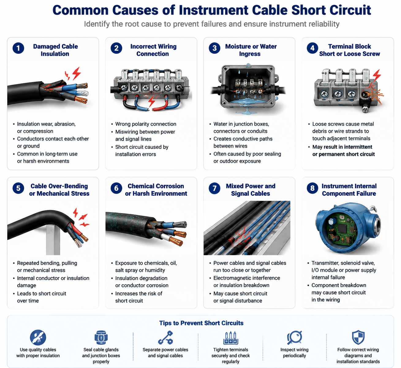
Common Causes of Instrument Wiring Short Circuits
1. Damaged Cable Insulation
Cable insulation may deteriorate due to:
- Aging
- Mechanical friction
- High temperature
- Chemical corrosion
- Improper installation
Damaged insulation can allow conductors to contact each other or the equipment grounding system.
2. Incorrect Wiring Connections
Common installation mistakes include:
- Incorrect power polarity connection
- Misconnected terminal blocks
- Wrong wiring during instrument replacement
- Shorting signal and power terminals
Always check wiring diagrams before commissioning new instruments.
3. Moisture and Water Ingress
Water entering junction boxes, cable glands, or instrument terminals can create conductive paths and cause short circuits.
Common causes:
- Poor cable gland sealing
- Damaged enclosure gasket
- Outdoor installation without proper protection
4. Component Internal Failure
Electrical components inside instruments may fail and create internal short circuits, such as:
- Transmitter circuit boards
- Solenoid valve coils
- Power supply modules
- PLC input/output modules
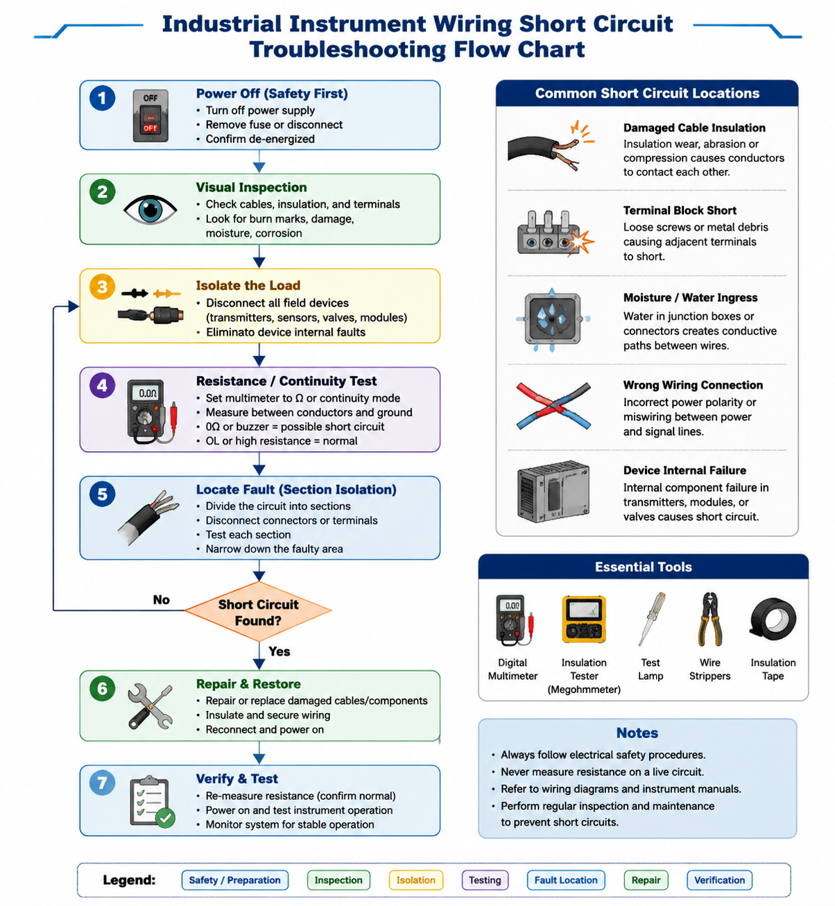
How to Troubleshoot Instrument Wiring Short Circuits
Step 1: Turn Off Power Before Inspection
Always disconnect the power supply before performing resistance measurements.
Recommended actions:
- Switch off the instrument power supply
- Remove the fuse or disconnect the power terminal
- Confirm the circuit is completely de-energized
Never measure resistance on a live circuit.
Step 2: Perform Visual Inspection
Check the wiring system carefully for:
- Burn marks
- Melted insulation
- Damaged cables
- Loose terminals
- Corrosion
- Water inside junction boxes
Visual inspection can often identify obvious problems quickly.
Step 3: Isolate the Load
Disconnect connected devices from the circuit, including:
- Sensors
- Transmitters
- Solenoid valves
- Control modules
This helps determine whether the short circuit comes from the cable or the connected device.
Step 4: Measure Resistance with a Multimeter
Set the multimeter to:
- Resistance mode (Ω)
- Continuity/buzzer mode
Measure between:
- Power line and ground
- Positive and negative terminals
- Signal line and power line
A reading close to 0Ω or continuous buzzer indicates a possible short circuit.
For industrial instruments containing electronic components, disconnect the device before testing to avoid incorrect readings.
Step 5: Locate the Fault by Section Isolation
If the short circuit location is unclear:
- Divide the wiring into different sections
- Disconnect terminal blocks or intermediate connectors
- Measure each section separately
- Continue narrowing down until the faulty area is identified
This method is commonly used for long instrument cable systems.
Step 6: Repair and Verify
After locating the fault:
- Replace damaged cables
- Repair insulation damage
- Replace faulty components
- Tighten loose terminals
After repair:
- Measure insulation/resistance again
- Confirm the circuit is normal
- Restore power
- Test instrument operation
Essential Tools for Short Circuit Troubleshooting
Common tools include:
- Digital multimeter
- Insulation resistance tester (megohmmeter)
- Test lamp
- Cable stripping tools
- Electrical insulation tape
- Wiring diagrams
For industrial systems, an insulation resistance tester is especially useful when checking cable insulation quality.
Difference Between Short Circuit, Open Circuit and Leakage Fault
| Fault Type | Characteristics | Testing Method |
|---|---|---|
| Short Circuit | Resistance close to zero | Resistance/continuity test |
| Open Circuit | Infinite resistance, broken connection | Continuity test |
| Leakage Fault | Reduced insulation resistance | Insulation resistance test |
Understanding the difference prevents incorrect troubleshooting.
Safety Precautions
When troubleshooting instrument wiring:
- Always disconnect power before resistance testing
- Never measure resistance on energized circuits
- Follow electrical safety procedures
- Use correct personal protective equipment
- Check wiring diagrams before reconnecting instruments
How to Prevent Instrument Wiring Short Circuits
To reduce wiring failures:
- Use proper cable glands and sealing methods
- Protect cables from mechanical damage
- Separate power cables and signal cables
- Check terminal tightening regularly
- Perform periodic insulation inspections
- Keep junction boxes clean and dry

Conclusion
Instrument wiring short circuits can cause unexpected downtime and damage to automation systems. By following a systematic troubleshooting process — power isolation, visual inspection, load separation, resistance measurement, section isolation, and verification — engineers can quickly identify and repair wiring faults.
Proper installation practices and regular maintenance are the best ways to prevent short circuit failures in industrial instrumentation systems.