
In industrial automation systems, 4-20mA current loops are one of the most widely used signal transmission methods.
Pressure transmitters, flow meters, level transmitters, temperature transmitters, and other field instruments commonly use 4-20mA signals to transmit measurement values to PLCs or DCS systems.
However, during field troubleshooting, a common question often confuses new technicians:
When measuring a 4-20mA signal with a multimeter, should it be connected in series or in parallel?
Many people instinctively think:
“A multimeter measures electrical signals, so why not connect it in parallel like a voltage measurement?”
This mistake can cause inaccurate readings, signal loss, or even interrupt the entire control loop.
The correct answer is:
A multimeter must be connected in series when measuring a 4-20mA current signal.
This article explains the reason from the basic electrical principles behind current loops.
1. What Is a 4-20mA Current Loop?
A 4-20mA signal is an analog current transmission standard widely used in industrial process control.
A field instrument converts a measured process variable into a proportional DC current signal:
- Pressure: 0-10 MPa
- Temperature: 0-200℃
- Flow rate: 0-100 m³/h
- Level: 0-10 m
The relationship is:
| Current Signal | Measurement Value |
|---|---|
| 4mA | 0% of range |
| 12mA | 50% of range |
| 20mA | 100% of range |
For example:
A pressure transmitter with a range of 0-10 MPa:
- 4mA = 0 MPa
- 12mA = 5 MPa
- 20mA = 10 MPa

2. Why Do Industrial Systems Use 4-20mA Instead of Voltage Signals?
The reason is mainly reliability.
2.1 Strong Noise Immunity
Unlike voltage signals, current signals are less affected by cable resistance and electromagnetic interference.
As long as the total loop resistance remains within the transmitter’s load limitation, the current flowing through the loop remains stable.
This makes 4-20mA suitable for long-distance industrial transmission.
2.2 Long Transmission Distance
4-20mA signals can typically travel hundreds of meters, even more than 1000 meters in suitable installations.
This is why they are commonly used in:
- Chemical plants
- Power plants
- Water treatment facilities
- Oil and gas systems
2.3 Live Zero Fault Detection
One important advantage of 4-20mA is the “live zero” concept.
The minimum signal is not 0mA but 4mA.
This allows the control system to distinguish between:
- 4mA → Normal zero measurement
- 0mA → Possible wire break, power failure, or instrument fault
3. Understanding the 4-20mA Loop Structure
A typical two-wire 4-20mA loop consists of:
- 24VDC power supply
- Field transmitter
- Signal cable
- PLC/DCS analog input module
The transmitter acts as a controlled current source.
It adjusts the loop current according to the measured process value.
The entire circuit is a series circuit.
In a series circuit:
The current is the same at every point in the loop.
Therefore, whether you measure near the transmitter or near the PLC/DCS input, the current value should be the same.
4. Why Must the Multimeter Be Connected in Series?
The key reason is the internal resistance of the multimeter.
Current Measurement
When the multimeter is set to the current (mA) range:
- Its internal resistance is very low
- Usually around several ohms
The purpose is to allow the measured current to flow through the meter.
Therefore:
Current measurement → Series connection
Voltage Measurement
When the multimeter is set to voltage mode:
- Internal resistance is very high
- Usually several megaohms
The purpose is to avoid affecting the measured circuit.
Therefore:
Voltage measurement → Parallel connection
The basic rule is:
| Measurement Type | Multimeter Resistance | Connection Method |
|---|---|---|
| Voltage (V) | Very high | Parallel |
| Current (A/mA) | Very low | Series |
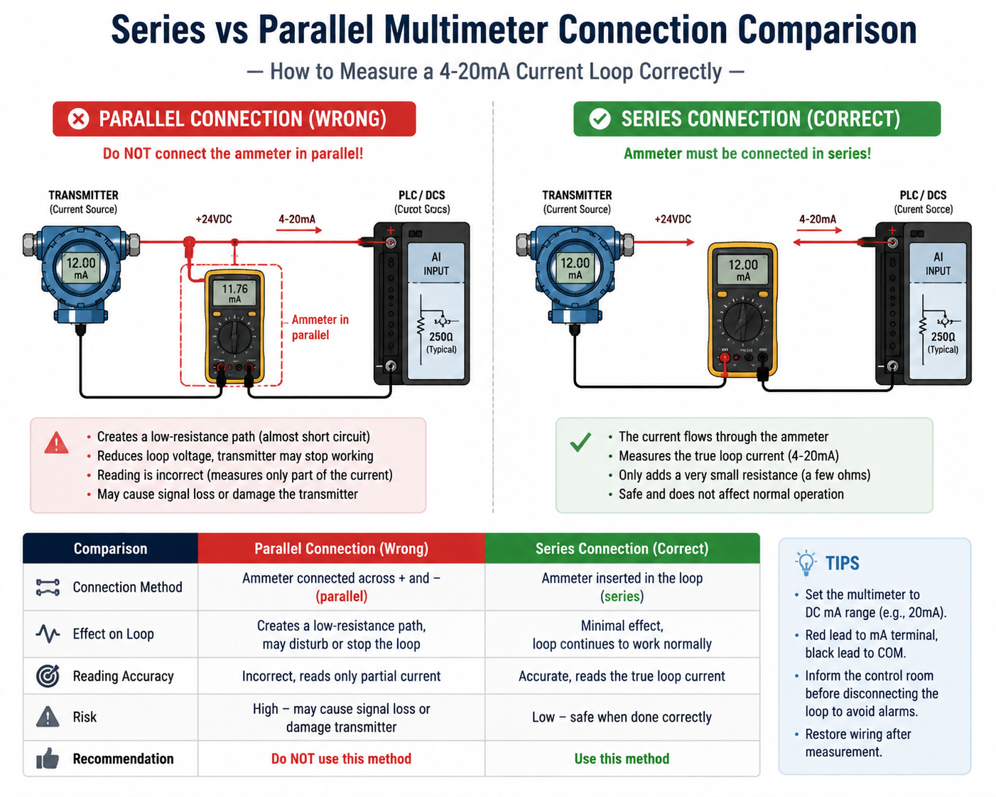
5. What Happens If You Connect the Multimeter in Parallel?
This is one of the most dangerous mistakes when measuring a 4-20mA loop.
A current meter has very low resistance.
If connected in parallel across the signal terminals, it creates an almost short circuit path.
For example:
Assume:
- 24VDC power supply
- 250Ω DCS input resistance
- Multimeter resistance: 5Ω
The meter creates a bypass path with only 5Ω resistance.
The transmitter can no longer maintain its normal operating voltage.
Possible results:
- Transmitter stops working
- DCS loses the signal
- Current reading becomes incorrect
- Loop fault alarm appears
In simple terms:
Connecting an ammeter in parallel is almost like shorting the signal loop.
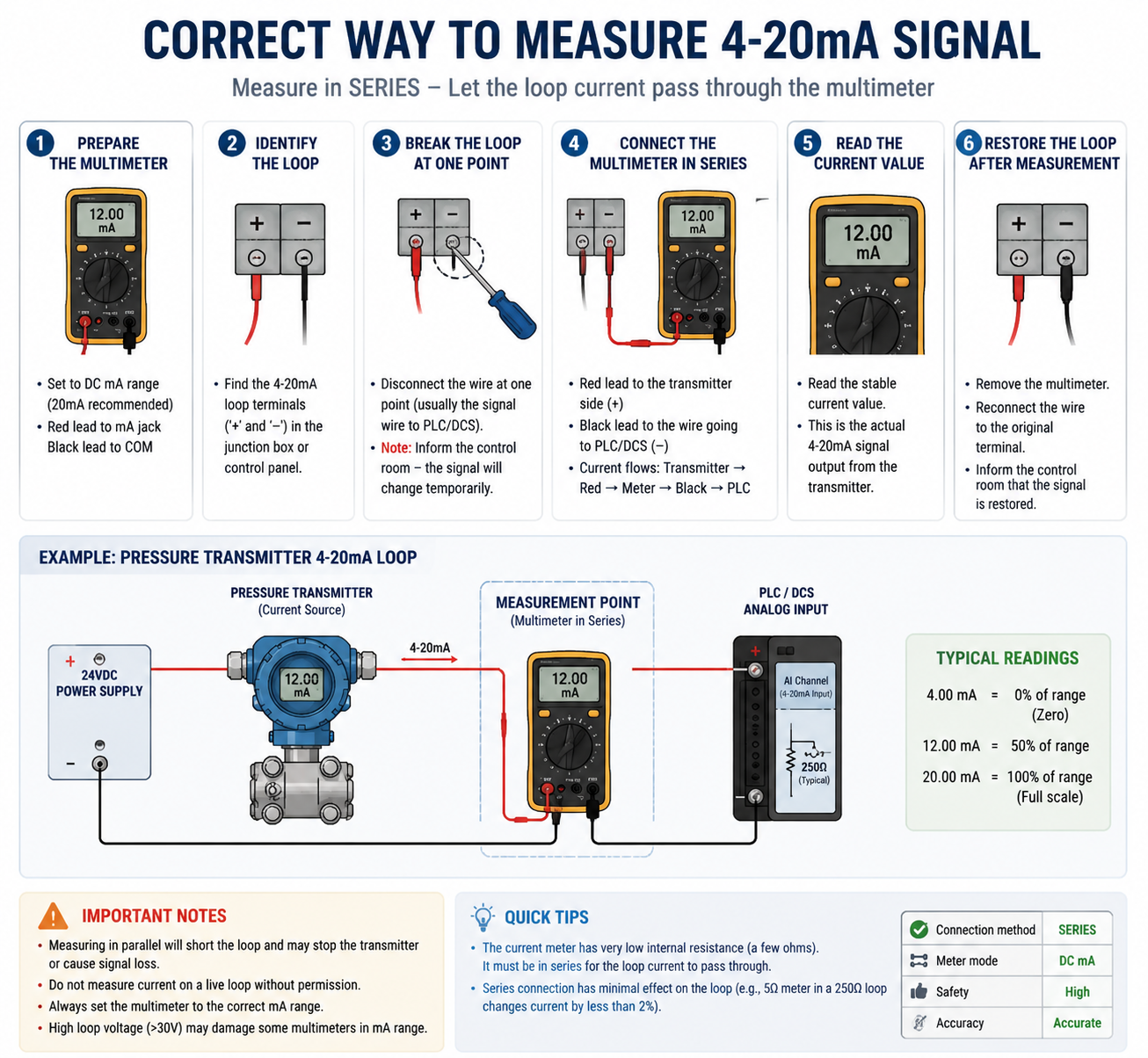
6. Correct Method to Measure a 4-20mA Signal
Step 1: Prepare the Multimeter
Set the multimeter:
- Mode: DC mA
- Red probe: mA terminal
- Black probe: COM terminal
Step 2: Break the Current Loop
Disconnect one point in the signal loop.
The multimeter must become part of the current path.
Example:
24VDC
  |
Transmitter
  |
Multimeter (mA)
  |
DCS / PLC Input
  |
0V
Step 3: Read the Current Value
The displayed value represents the actual transmitter output.
Examples:
- 4mA → Zero point
- 12mA → 50% measurement
- 20mA → Full scale
7. Common Mistakes When Measuring 4-20mA
7.1 Using Voltage Mode Instead of Current Mode
If the meter is set to voltage mode:
- The loop current cannot flow through the meter
- The reading may show zero
- The measurement is meaningless
7.2 Selecting the Wrong Current Range
For 4-20mA signals:
Use:
- mA range
- High resolution mode
Avoid using a large ampere range because the resolution may be too low.
7.3 Reversing the Probe Polarity
If the probes are connected backward:
Modern digital multimeters usually display a negative value.
Example:
-12.00mA
The circuit is normally not damaged, but the probes should be reversed for a positive reading.
8. How to Measure 4-20mA Without Disconnecting the Loop?
In some critical processes, disconnecting the signal loop is not allowed.
A common alternative method is measuring the voltage across the PLC/DCS sampling resistor.
For example:
If the input resistor is:
250Ω
and the measured voltage is:
2.5V
Using Ohm’s law:
I = U / R
I = 2.5V / 250Ω
I = 10mA
This method:
Advantages:
- No interruption to the control system
- Safe for running processes
Disadvantages:
- Requires knowing the exact resistor value
- Accuracy depends on resistor tolerance
9. Quick Diagnosis of 4-20mA Signal Problems
| Current Reading | Possible Condition |
|---|---|
| 0mA | Power failure, broken wire, open circuit |
| 3.5-3.9mA | Instrument fault output |
| 4mA | Zero measurement |
| 4-20mA changing | Normal operation |
| 20mA | Full scale measurement |
| Above 20.5mA | Over-range or fault condition |
| Unstable signal | Wiring problem or electrical interference |

10. Final Rule: Remember This Principle
The reason a multimeter must be connected in series for 4-20mA measurement comes from the basic electrical characteristics:
- Current meters have very low resistance → must be connected in series.
- Voltage meters have very high resistance → must be connected in parallel.
For industrial instrumentation:
Measure current in series. Measure voltage in parallel.
Understanding this simple rule helps technicians correctly troubleshoot:
- Pressure transmitters
- Flow meters
- Level transmitters
- Temperature transmitters
- PLC/DCS analog input loops
and prevents unnecessary shutdowns caused by incorrect measurement methods.