1. How Radar Level Meters Measure Liquid Level
Radar level meters use the Time-of-Flight (TOF) principle: the transmitter emits a microwave pulse, which reflects off the liquid surface and returns to the sensor. The instrument calculates the distance based on the round-trip travel time.
Formula:
where:
- = distance to liquid surface
- = speed of light (~3×10⁸ m/s)
- = round-trip time (picoseconds)
The frequency determines the wavelength, beam divergence, and energy concentration, which directly affect measurement precision, beam angle, and suitable application scenarios.
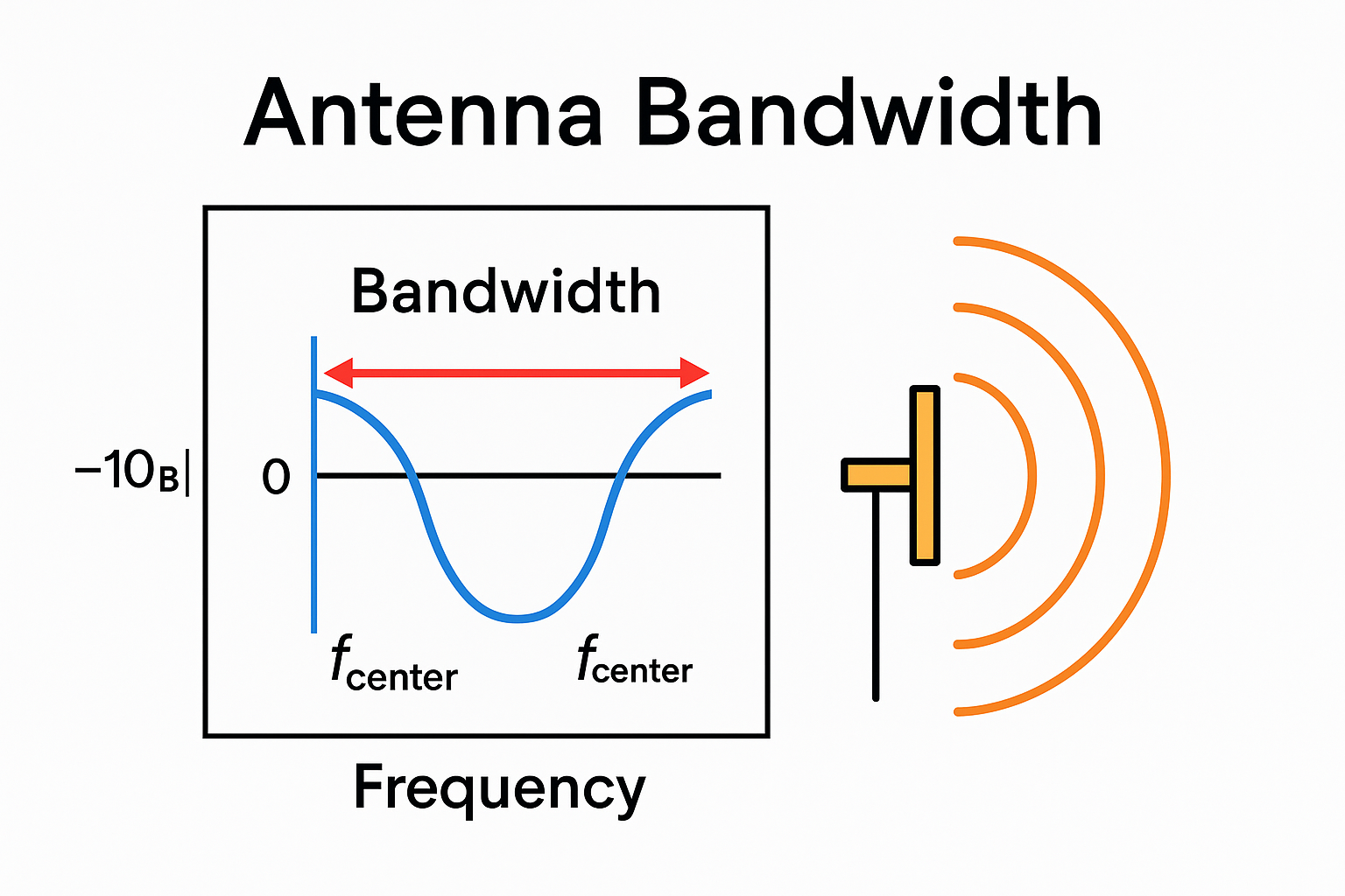
2. Frequency Comparison: Wavelength and Beam Characteristics
| Frequency | Wavelength | Visual Analogy |
|---|---|---|
| 6 GHz | ~50 mm | Fist-sized wave |
| 26 GHz | ~11 mm | Fingernail-sized wave |
| 80 GHz | ~3.7 mm | Needle-thin wave |
- Higher frequency → shorter wavelength, narrower beam, higher resolution.
- Lower frequency → longer wavelength, wider beam, better penetration through foam or vapor.
3. Low Frequency vs High Frequency
| Feature | Low Frequency (6–10 GHz) | High Frequency (26–80 GHz) |
|---|---|---|
| Wavelength | 30–50 mm | 3.7–11 mm |
| Antenna Size | Large (horn type) | Small (flat antenna possible) |
| Beam Angle | 15°–30° | 3°–8° |
| Measurement Accuracy | ±5–10 mm | ±1–2 mm |
| Range | Up to 20–30 m | 30–100 m |
| Foam Penetration | Strong | Weak |
| Corrosive Gas Resistance | Good | Requires tight sealing |
| Small Tank Suitability | Poor | Good |
| Cost | Lower | Higher (especially 80 GHz) |
Key Point: “Penetration” refers to passing through foam or vapor, not the liquid itself. Radar always measures reflections from the liquid surface; it does not penetrate the liquid.
4. Why Low Frequency Penetrates Foam Better
Foam consists of numerous microbubbles, creating a heterogeneous medium. Microwaves passing through foam experience scattering and absorption.
Scattering principle:
- Rayleigh scattering: scattering is weak if obstacles << wavelength; strong if obstacle ~ wavelength.
- Bubble size in foam: 0.1–5 mm
Example:
- 6 GHz (λ ≈ 50 mm) → bubbles << wavelength → weak scattering → good penetration
- 80 GHz (λ ≈ 3.7 mm) → bubble ~ wavelength → strong scattering → significant signal loss
Water vapor effect:
- Water molecules absorb microwaves; higher frequency is more affected.
- In high-temperature or high-vapor tanks, low-frequency radar suffers less attenuation.
5. Beam Angle and Tank Installation
Beam angle determines whether the radar can fit in the tank without interference. Narrow beams are better for small tanks to avoid reflections from walls or internal structures (stirrers, coils).
| Tank Diameter | Recommended Frequency | Reason |
|---|---|---|
| DN < 500 mm | 80 GHz | Narrow beam avoids wall reflections |
| DN 500–2000 mm | 26 or 80 GHz | Depends on internal structures |
| DN > 2000 mm | 6 or 26 GHz | Space allows low-frequency use |
| Tanks with agitators | 80 GHz | Narrow beam can avoid interference zones |
Near-end blind zone: typically 50–200 mm from antenna. High-frequency radar has a smaller blind zone.
6. Why 80 GHz Became Mainstream
Since 2015, 80 GHz FMCW radar has rapidly dominated the market due to:
- Precision: ±1 mm vs ±5 mm for 6 GHz
- Small antenna size: fits small containers
- Narrow beam angle: minimizes false echoes
- Extended range: up to 100 m
- Cost reduction: mass production made 80 GHz comparable to 26 GHz
Limitations:
- High-foam conditions (fermentation tanks, paper black liquor) → prefer low-frequency or guided-wave radar
- High temperature/pressure → requires advanced sealing
- Corrosive gases → antenna sealing lifetime must be considered
7. Frequency Selection Guidelines
| Priority | Application |
|---|---|
| 80 GHz | Small containers (DN < 1000 mm), tanks with agitators/heating coils, bypass pipe measurement, solid silos, high-precision trade tanks |
| 6 GHz | Large tanks, high foam, high-temperature vapor, strongly corrosive gases, cost-sensitive applications |
| 26 GHz | Medium tanks (DN 1000–3000 mm), moderate foam, mature spare parts availability |
Unsuitable scenarios:
- Vacuum tanks → radar works well (microwaves travel better in vacuum)
- Extremely low dielectric (<1.5) → weak reflection, use guided-wave radar
- Metal mesh tanks → signal leakage
- Highly turbulent or splashing without clear liquid surface
8. Common Misconceptions
- “Higher frequency is always better.”
- False: high-frequency 80 GHz may fail in high-foam tanks.
- “Low frequency can be used everywhere.”
- False: wide beam may hit walls in small tanks → false echoes; accuracy is lower; large antenna may not fit.
- “Radar penetrates the liquid to measure tank bottom.”
- False: radar only reflects from liquid surface; sub-liquid measurement requires ultrasonic or float level sensors.
9. Summary
- Radar measures liquid level via microwave reflection, not penetration.
- 6 GHz (low frequency): long wavelength → strong foam/vapor penetration, suitable for large tanks and high-foam conditions; lower accuracy
- 80 GHz (high frequency): narrow beam → high accuracy (±1 mm), suitable for small tanks and complex internal structures; sensitive to foam
- 26 GHz: transitional frequency, widely used, balanced accuracy
- 80 GHz is mainstream but not universal—select low-frequency or guided-wave radar for high-foam conditions
- Narrower beams reduce interference from tank walls and structures; small tanks → prefer high frequency