In modern electronic engineering and industrial automation, a signal generator is an essential instrument used to provide various electrical signals for testing, calibration, simulation, and troubleshooting.
It can generate multiple types of signals such as:
Voltage signals
Current signals
Resistance simulation
Thermocouple signals
RTD signals
Frequency and pulse outputs
Signal generators are widely used in PLC systems, industrial control panels, instrumentation calibration, communication systems, and laboratory testing.
This article explains how a signal generator works, its main features, and where it is commonly used in industrial applications.
What Is a Signal Generator?
A signal generator is a device that produces electrical signals with controlled parameters such as:
amplitude
frequency
waveform
phase
output type
It is mainly used to simulate real sensor outputs and test the response of receiving equipment.
For example, in industrial automation, it can simulate:
4–20mA 0–10V Pt100 K type thermocouple pulse frequency
This allows engineers to test control systems without connecting actual field instruments.
Main Features of a Signal Generator
1. Multiple Signal Output Types
One of the biggest advantages is its ability to output different signal types.
Voltage Output
It can generate multiple waveforms such as:
sine wave
square wave
triangle wave
pulse wave
These signals are widely used in electronic circuit testing and communication equipment debugging.
Current Output
Current output is widely used in industrial instrumentation.
The most common standard is:
4–20mA
This is widely used for:
pressure transmitters
flow meters
level transmitters
temperature transmitters
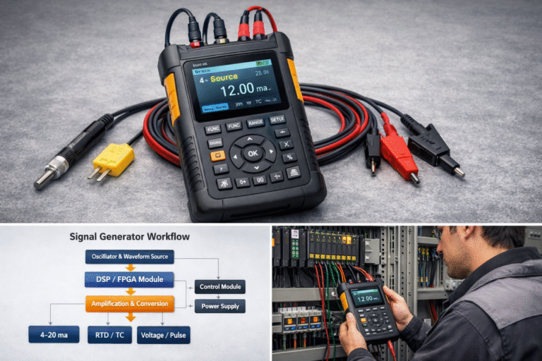
For example, engineers often use a signal generator to simulate 12mA and verify whether the PLC input displays 50% of range correctly.
Resistance Simulation
It can simulate various resistance values for testing circuits and measuring devices.
This is especially useful for:
RTD simulation
load resistor testing
circuit calibration
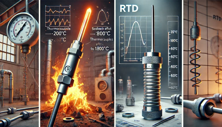
Thermocouple and RTD Simulation
This is one of the most important functions in industrial instrumentation.
It can simulate:
Pt100
Pt1000
K type
J type
E type thermocouples
This function is commonly used for temperature transmitter calibration and DCS system testing.
Working Principle of a Signal Generator
The internal structure mainly consists of four modules:
signal generation module
signal processing module
control module
power supply module
Signal Generation Module
This is the core part of the device.
It generates the original waveform through:
oscillator circuits
DSP chips
FPGA modules
microprocessors
For analog waveforms, oscillators are commonly used.
For digital signals and complex waveforms, DSP or FPGA is preferred.
Signal Processing Module
This module performs:
amplification
filtering
modulation
signal conversion
For example, it converts voltage signals into current outputs such as 4–20mA.
Control Module
The control module receives user commands and precisely adjusts:
frequency
voltage
current
resistance value
temperature simulation
This ensures high output accuracy and stability.
Power Supply Module
A stable power supply ensures reliable output performance.
This is especially important for high-precision calibration applications.
Industrial Applications
PLC and DCS System Testing
This is one of the most common applications.
Engineers use signal generators to simulate field instruments and verify:
analog input channels
analog output channels
alarm logic
interlock systems
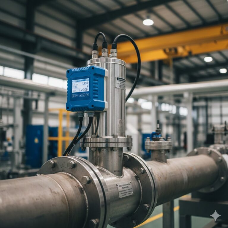
Flow Meter Calibration
In flow measurement systems, it is often used to simulate:
pulse output
4–20mA flow signals
frequency signals
This helps verify PLC total flow reading and control logic.
This is highly relevant for your instrumentation business.
Temperature System Calibration
It is widely used to simulate RTD and thermocouple signals for:
temperature transmitters
controllers
paperless recorders
SCADA systems
Communication Equipment Testing
In communication systems, it can generate modulation signals such as:
AM
FM
PM
QAM
PSK
Used for transmitter and receiver testing.
How to Choose the Right Signal Generator
When selecting a signal generator, customers should consider:
Output Type
4–20mA
voltage
resistance
RTD
thermocouple
pulse
Accuracy
0.05%
0.1%
0.2%
Portable or Bench Type
field calibration
laboratory testing
Communication Interface
USB
RS485
HART
Conclusion
A signal generator is an essential tool for industrial instrumentation, PLC debugging, and process control system testing.
Whether for flow meters, pressure transmitters, or temperature systems, it helps engineers improve commissioning efficiency and ensure system accuracy.
If you are looking for a portable industrial signal generator for 4–20mA, RTD, and thermocouple calibration, feel free to contact us for datasheet and quotation.