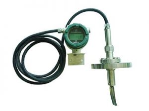
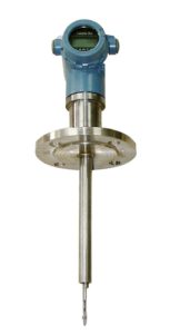
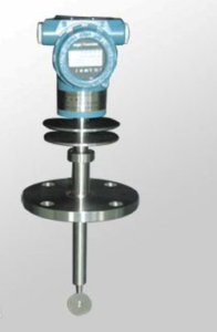
The plug-in target flow meter is a new type of capacitive force induction flow plug-in target flowmeter developed on the basis of the traditional target flow meter and with the development of new sensors and microelectronics technology. It has an orifice plate Flowmeters such as vortex and vortex flowmeters have no moving parts, and at the same time have high sensitivity, accuracy comparable to positive displacement flowmeters, and a wide range.
● Wide range of applicable pipe diameter: Φ10~Φ2000 or larger.
● Wide applicable temperature range: -196°C ~ 500°C.
● Suitable for high/low-pressure working conditions: 0~42MPa.
● Applicable to various media: gas, liquid (including high viscosity liquid, slurry), steam.
● Suitable for low-velocity media, the lowest measurable flow velocity is 0.08m/s.
Working Principle
When the medium flows in the measuring tube, its own kinetic energy produces a pressure difference with the target plate, which generates a force on the target plate, causing the target plate to produce a small amount of displacement. The force is proportional to the square of the medium flow rate. , Its mathematical formula: F = Cd·A·ρ·V2/2 F: Force on the target board Cd: fluid resistance coefficient A: Axial projection area of target plate to measuring tube ρ: Medium density under working conditions V: The characteristic flow rate of the medium in the measuring tube The force received by the target plate is transmitted through the target rod to cause a slight change in the elastic body of the sensor, which is converted by a circuit to output a corresponding electrical signal. The use of capacitive force sensors is the key core of the new product to achieve high precision and high stability.
It has completely changed the original strain-type target flowmeter with large temperature drift, poor overload (impact) resistance, and static sealing points.
Various limitations not only give play to the original technical advantages of target flow meters but also have measurement accuracy comparable to positive displacement flow meters.
In addition to its unique anti-interference and anti-impurity performance, in addition to being able to replace conventional flow measurements.
The flow metering problem of the gas, especially in the working conditions of small flow, high viscosity, easy to condense and easy to block, high and low temperature, strong corrosion, strong vibration, and other flow measurement difficulties.
It has been widely used in flow measurement in various fields such as metallurgy, petroleum, chemical industry, energy, food, and environmental protection.
Technical parameter
Detailed description: Nominal diameter: 100~2000mm Nominal pressure: 0.6~10.0MPa Medium temperature: 10℃~70℃ Accuracy level: 0.5; 1.0 Shell material: 304; 316L; or according to user requirements Power supply mode: built-in 3.6V lithium battery; 24VDC Output signal: 4~20mA; pulse; 0~10V; RS232/485; HART Protection level: IP65; IP67; IP68 Explosion-proof grade: intrinsically safe ExiaIICT4; flameproof ExdIIBT4/ExdIICT4 Scope of application: measurement of various liquid and gaseous media in large and medium diameter pipelines.
Main product connection and installation dimensions: a. The short-circuit flange implements the national standard: the relevant technical requirements in the GB/T9112, 9113, 9115, 9116, 9117-2000 standards; b. 0.6MPa; 1.0MPa; 2.0MPa; 5.0MPa; 6.3MPa; 10.0MPa are all special orders; c. Standard flanges of other countries (Japanese standard, American standard, German standard, etc.) are all special orders; d. When the pipe diameter is less than DN300, use DN50 flange short-circuit; when pipe diameter ≥DN300, use DN100 flange short-circuit; e. The medium fluid flows from top to bottom or bottom to top, please specify when ordering: right view left view (display meter head).
Features
- The whole instrument has a solid structure and no moving parts, plug-in structure, easy to disassemble;
- A variety of anti-corrosion and high and low-temperature resistant materials (such as Hastelloy, titanium, etc.) can be used;
- The whole machine can be made into a fully sealed, no dead angle (welded form), without any leakage points, and can withstand 42MPa high pressure;
- The self-checking procedure is set in the instrument, and the fault phenomenon is clear at a glance;
- The sensor is not in contact with the measured medium, there is no wear of parts, and it is safe and reliable to use;
- The dry calibration method can be used on the spot, that is, the weight hanging method is used. The single key operation can complete calibration;
- There are a variety of installation methods to choose from, such as an online plug-in, the installation cost is low;
- With integrated temperature and pressure compensation, directly output quality or standard;
- With optional small-signal removal, non-linear correction, and filter time optional;
- It can accurately measure the flow of gas and liquid under various normal temperature, high temperature 500 degrees, and low temperature -200 degrees;
- The measurement is accurate, and the accuracy can reach 0.2%;
- Good repeatability, generally 0.05%~0.08%, fast measurement;
- The pressure loss is small, only about 1/2△P of the standard orifice plate;
- Strong anti-interference and anti-impurity ability;
- The measuring range can be changed by replacing the baffle (target) according to actual needs;
- Low-power battery on-site display, which can directly read the displayed value online, and the display can read instantaneous and cumulative flow and percentage bar graphs at the same time;
- Installation is simple and convenient, and easy to maintain;
- Multiple output forms, capable of transmitting various parameters remotely;
- Strong shock resistance, pulsating flow can be measured within a certain range.
Typical application
Gases: coal gas, air, hydrogen, natural gas, nitrogen, liquefied petroleum gas, hydrogen peroxide, flue gas, methane, butane, chlorine, etc.
Liquids: heavy oil, paraffin, asphalt, sulfuric acid, edible oil, residual oil, acetone, diesel, mine water, detergent, soy sauce, gasoline, silicone oil, syrup, solvent, perfume, seawater, aviation kerosene, soap ketone water, glucose, Rapeseed acid, saltwater, paste, ink, coolant, ethylene glycol, mineral oil, liquid sugar, hydrochloric acid, car paint, resin, butter, rape oil, liquid oxygen, shampoo, toothpaste, gel, fuel, milk, Bleach, conditioner, soda, additives, cleaning agents, alkaline, ammonia, marine oil, chemical reagents, kerosene, glycerin, dyes, water, nitric acid, high boiling point organic solutions, lard, additives, alcohol, oil, ethylene, Polypropylene, toluene, etc.
Troubleshooting
(The flowmeter is equipped with a fault self-check program, and the user can find out some of the reasons through the display!)
- When the flow rate of the measured medium in the pipeline is zero, the instantaneous flow value indicated by the flowmeter is not zero. The main reasons for this phenomenon are a. The level of the flowmeter before and after installation is inconsistent, so that the target piece and the target rod produce axial horizontal component force due to the inclination, resulting in the instantaneous flow; b. The flowmeter is running for a long time, and the internal stress of the sensor changes slightly; c. During installation or operation, severe overload causes zero drift; The above three methods can refer to the steps and methods of clearing the flowmeter. d. Poor grounding of the flowmeter housing; Solution: the user re-grounds. e. The target piece, target rod, and measuring tool are jammed by debris; Treatment method: close the front and rear valves of the flowmeter, loosen the connecting bolts between the flowmeter transition part and the measuring tube with a tool, and gently shake the transition part or take it out, and reset it as it is after cleaning the debris.
- The indication value increases abnormally during the working process of the flowmeter. The main reasons for this phenomenon are a. There is filamentous and ribbon-shaped debris hanging on the target and the target rod; Treatment method: Refer to the method of handling debris. b. Under high junction conditions, the target sheet and the target rod will form a serious bond, which increases the projected area of the target plate of the force-bearing element along the axis of the measuring tube, that is, the annular flow area between the target sheet and the measuring tube decreases, and then the target Under the flow, the force on the sensor increases, which eventually leads to an abnormal increase in the flow indication; Processing method: remove the transition parts, use tools to remove the target piece and target rod and the masonry on the inner wall of the measuring tube.
- The measurement error is large, and there are many reasons for this phenomenon. The main reasons are the following: a. The relative concentricity of the flow meter and the connecting pipeline is greatly misaligned during installation, and the sealing gasket is not concentric, thus forming a throttling resistance, which greatly affects the measured medium Mass flow regime Solution: Adjust the installation status. b. The straight pipe sections before and after the flowmeter are too short, and elbows and valves are installed directly in front of the flowmeter, which greatly interferes with the flow state of the measured medium; Treatment method: install according to the instructions or calibrate the flowmeter on the spot. c. Leakage of bypass pipeline; Treatment method: check and replace the bypass pipeline. d. Band-shaped debris is wrapped around the target, which increases the force on the target; Treatment method: Refer to the previous method of handling debris.
- The flowmeter has no indication or no signal. The main reasons are as follows: a. Poor power contact or fall off; Treatment method: For flow meters with batteries, check whether the batteries are installed securely, whether the contacts are good, and whether the batteries have electricity. For the external power supply, Check whether the connection between the connecting wires is intact, whether the wires are conductive, and whether the external power supply is normal. b. The flowmeter circuit is damaged; Treatment method: return to the factory for repair. c. The display screen is damaged; Treatment method: return to the factory for replacement. d. The user signal receiving system fails; Treatment method: check and troubleshoot.
- The indicated value is always zero during the operation of the flow meter. The main reasons for this phenomenon are a. The force-receiving element (target) falls off, causing the sensor to be unable to sense; Treatment method: Assemble targets of the same specification. b. The flowmeter sensor has no voltage output signal; Processing method: Firstly, judge whether the sensor is damaged. The specific method is to see whether the sensor data has changed. c. The measured medium flow is too small, which is lower than the minimum scale flow of the flowmeter; Treatment method: return to the factory to replace the stress component.