
Why does a Coriolis mass flow meter suddenly show an inaccurate reading? Is the sensor faulty, or is something wrong with the installation?
A 0.5% discrepancy in custody transfer measurement can quickly turn into an argument between the process team, instrumentation engineers, and the metering department.
Everyone may initially suspect that the flow meter is inaccurate. However, the actual cause could be much simpler: the meter body has been carrying the weight of the pipeline. As the pipeline expands and contracts with temperature changes, mechanical stress is transferred to the measuring tubes, causing the zero point to drift.
Coriolis mass flow meters are among the most sophisticated industrial flow measurement instruments. They measure mass flow directly, provide density and temperature measurements, and generally do not require upstream or downstream straight pipe runs in the same way as many conventional flow meters.
However, their measurement principle also makes them sensitive to mechanical stress, vibration, gas entrainment, and improper installation.
Understanding how the measuring tubes vibrate, how phase difference represents mass flow, and why zero calibration must be performed under the correct conditions is essential for reliable operation.
This guide explains the working principle, installation requirements, commissioning procedures, zero calibration, and common troubleshooting methods for Coriolis mass flow meters.
1. How Does a Coriolis Mass Flow Meter Work?
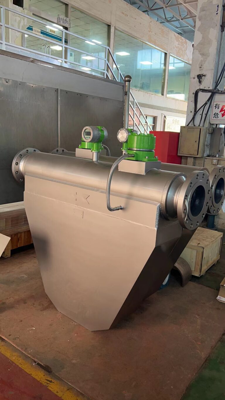
A Coriolis mass flow meter uses the interaction between vibrating measuring tubes and flowing fluid to determine mass flow rate.
Its measurement process can be divided into four stages.
Step 1: Measuring Tube Vibration
An electromagnetic driver excites the measuring tubes at or near their natural resonant frequency.
In many designs, two measuring tubes vibrate in opposite directions. The vibration amplitude is extremely small, typically on a microscopic scale.
Step 2: Generation of Coriolis Forces
When fluid flows through the vibrating tubes, Coriolis forces act on the moving fluid.
These forces cause the measuring tubes to undergo a small additional deformation or twisting motion.
The direction and magnitude of this effect depend on the direction and rate of mass flow.
Step 3: Phase Difference Detection
Two pickup sensors are installed at different positions along the measuring tubes.
They detect the vibration signals at the inlet and outlet sides.
When there is no flow, the signals have a defined phase relationship. When fluid flows through the tubes, the Coriolis effect produces a measurable phase shift.
The greater the mass flow rate, the greater the phase difference, within the instrument’s calibrated operating range.
Step 4: Mass Flow Calculation
The transmitter processes the phase difference and converts it into a mass flow measurement.
A simplified relationship is:
Mass flow rate = Calibration factor x Phase difference
The actual calculation is more sophisticated and depends on the sensor design, mechanical characteristics, signal processing, and factory calibration.
How Is Density Measured?
Density is determined using the resonant frequency of the measuring tubes.
When the density of the fluid changes, the effective vibrating mass of the measuring system changes, resulting in a change in resonant frequency.
The transmitter uses this relationship to calculate fluid density.
A temperature sensor also monitors the measuring tube temperature, allowing the transmitter to compensate for temperature-related changes in the mechanical properties of the sensor.
As a result, one Coriolis mass flow meter can provide several process variables:
- Mass flow rate
- Fluid density
- Fluid temperature
- Calculated volumetric flow rate
- Totalized flow
This multi-variable capability makes Coriolis technology particularly valuable in custody transfer, batching, chemical dosing, and precision process control.
Why Is Zero Stability So Important?
Consider a DN80 Coriolis flow meter with a maximum flow rate of 50 t/h.
Assume its 4–20 mA output is configured for 0–50 t/h.
The output relationship is:
- 4 mA = 0 t/h
- 20 mA = 50 t/h
- 1 mA = 3.125 t/h
- 0.01 mA = 31.25 kg/h
A small electrical or measurement offset can therefore become significant, especially at low flow rates.
For example, a 0.05 mA output offset corresponds to approximately 156.25 kg/h.
At an actual flow rate of 5 t/h, this represents an error of approximately 3.13%.
This example illustrates why zero stability is particularly important when a meter operates at a small percentage of its measuring range.
Note that zero stability is an instrument performance specification, while zero offset is the actual deviation observed under zero-flow conditions. They should not be treated as the same parameter.
2. Main Components of a Coriolis Mass Flow Meter
Although different manufacturers use different sensor designs, the main components generally include the following.
1. Measuring Tubes
The measuring tubes may have U-shaped, double-U, straight-tube, or other configurations.
Common materials include 316L stainless steel and corrosion-resistant alloys such as Hastelloy C-22.
The measuring tubes are the core sensing elements. Their mechanical characteristics directly influence measurement performance.
Deposits, corrosion, erosion, and internal blockage can change the effective mass and stiffness of the vibrating system.
2. Electromagnetic Driver
The driver consists of an electromagnetic coil and magnetic components.
Its function is to maintain the required tube vibration.
Changes in drive gain or excitation demand can provide useful diagnostic information about abnormal operating conditions.
However, high drive gain alone does not identify a specific fault. It should be evaluated together with other diagnostic parameters and process conditions.
3. Pickup Sensors
Pickup sensors are installed at different positions along the measuring tubes.
They detect tube vibration and provide the signals used to determine phase difference.
Loose connections, moisture, damaged cables, or weak signals may affect measurement stability.
4. Temperature Sensor
A temperature sensor measures the temperature of the measuring tube assembly.
The transmitter uses this information to compensate for temperature-related changes in sensor characteristics.
5. Housing and Transmitter
The sensor housing protects the measuring tubes and associated components.
The transmitter processes the sensor signals and provides local display and communication functions.
Common output options include:
- 4–20 mA
- Pulse output
- HART
- Modbus
- Other industrial communication protocols, depending on the model
3. Installation Requirements: Prevent Zero Drift Before Commissioning
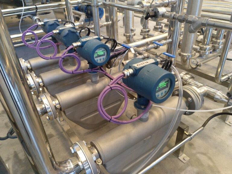
Many Coriolis flow meter problems are caused by installation conditions rather than electronic failure.
Before performing zero calibration, check the following items.
Check the Flow Direction
Confirm that the flow direction matches the arrow marked on the sensor body.
Reverse installation may result in negative flow indication, depending on the transmitter configuration.
Check Flange Alignment
The inlet and outlet flanges should be properly aligned.
Tighten the bolts evenly in a crosswise sequence.
Never use the Coriolis meter body to pull misaligned pipelines into position.
Excessive mechanical stress can affect the measuring tubes and compromise zero stability.
Provide Independent Pipe Supports
This is one of the most important installation requirements.
The upstream and downstream pipelines should have suitable independent supports.
The flow meter should not carry excessive pipeline weight or absorb unnecessary thermal expansion forces.
A missing pipe support can create mechanical stress that changes with operating temperature.
This is a common reason for zero drift in industrial installations.
Check Straight Pipe Requirements
Most Coriolis flow meters do not require long upstream and downstream straight pipe sections.
However, this does not mean installation location is irrelevant.
Avoid locations with excessive external vibration, mechanical interference, or difficult maintenance access.
Always follow the manufacturer’s installation instructions for the specific sensor model.
Remove Entrained Gas
For liquid applications, the measuring tubes should remain completely filled during normal operation.
Air or gas bubbles inside the measuring tubes can cause unstable readings, density errors, and increased drive gain.
Recommended practices include:
- Install the meter in an orientation that helps maintain full measuring tubes.
- Provide appropriate venting points where necessary.
- Slowly fill the pipeline during commissioning.
- Avoid operating conditions that cause pump cavitation.
- Follow the manufacturer’s recommended mounting orientation.
Check Grounding and Cable Shielding
Follow the manufacturer’s wiring diagram for grounding and cable shielding.
Keep signal cables away from high-power cables, variable-frequency drives, motors, and welding equipment where possible.
Incorrect grounding or electromagnetic interference may cause unstable transmitter signals.
Allow Temperature Stabilization Before Zero Calibration
Before zero calibration, allow the meter and process conditions to stabilize.
The measuring tubes must be completely filled, the fluid must be stationary, and the temperature must be reasonably stable.
A stabilization period of around 10 minutes can be a useful starting point, but the manufacturer’s instructions and actual process conditions should determine the final requirement.
4. HART Configuration and Signal Adjustment
Many Coriolis transmitters support HART communication, allowing engineers to access process variables, configuration parameters, and diagnostic information.
Before changing any settings, read the existing transmitter configuration.
Read PV, SV, and TV
Depending on the transmitter configuration, these variables may represent:
- PV: Mass flow rate
- SV: Fluid density
- TV: Fluid temperature
Check whether the three variables are consistent with the actual process conditions.
For example, an unexpectedly low or unstable density reading may indicate gas entrainment or another abnormal measurement condition.
However, density changes can also be caused by genuine process variations.
Check Measurement Units and Range
Confirm that the transmitter uses the correct engineering units.
Common examples include:
- kg/h
- t/h
- kg/min
- kg/s
Check the Lower Range Value (LRV) and Upper Range Value (URV).
The transmitter range, 4–20 mA output range, and DCS scaling must be consistent.
Perform 4–20 mA Output Trim When Necessary
A digital-to-analog (D/A) trim is used to correct the transmitter’s analog output.
For example, a technician can use a calibrated multimeter to check whether the actual output matches the commanded 4 mA and 20 mA values.
The procedure must follow the transmitter manufacturer’s instructions.
Important: D/A trim corrects the analog output signal. It does not calibrate the mass flow measurement itself and cannot correct mechanical zero drift.
Check Damping and Low Flow Cutoff
Damping controls how quickly the displayed or transmitted measurement responds to changes.
Excessive damping can hide genuine process fluctuations.
Insufficient damping may cause unstable readings in the control system.
Low flow cutoff should also be configured carefully.
If the cutoff threshold is too high, the transmitter may suppress real low-flow measurements.
This is particularly important in batching, chemical dosing, and custody transfer applications.
Check Diagnostic Information
Many modern transmitters provide diagnostic information based on NAMUR NE107 categories:
- Failure
- Function Check
- Out of Specification
- Maintenance Required
The actual diagnostic implementation varies by manufacturer.
Do not rely only on the presence or absence of an alarm. Review the diagnostic code and operating conditions together.
5. Zero Calibration and Flow Range Configuration
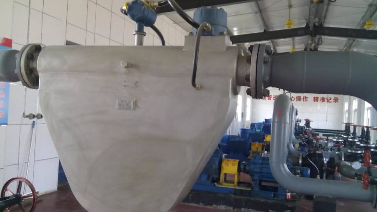
Zero calibration is one of the most important procedures for a Coriolis mass flow meter.
However, it must be performed under the correct conditions.
Zero Calibration: Establishing the Zero-Flow Reference
Before starting zero calibration, confirm the following:
- The measuring tubes are completely filled with the process fluid.
- There is no actual flow through the meter.
- There are no trapped gas bubbles.
- The fluid temperature is stable.
- The inlet and outlet valves are fully closed and do not leak internally.
- The meter is not subjected to abnormal mechanical stress.
Once these conditions are satisfied, execute the Zero Calibration function through the transmitter menu or approved configuration tool.
The transmitter establishes its zero-flow reference based on the current sensor condition.
Do not repeatedly perform zero calibration to hide an underlying mechanical or process problem.
If the zero offset is significantly different from the historical baseline, investigate the cause before recalibrating.
Flow Range Configuration
The URV should be selected according to the expected operating range and the meter’s rated capacity.
For example, if the normal operating flow rate is 40 t/h, the configured range may be selected to provide sufficient measurement headroom without sacrificing low-flow resolution.
The actual range must remain within the manufacturer’s specified measuring limits.
Three Different Calibration Activities
It is important to distinguish between the following procedures.
1. Range Configuration
Sets the measurement range and the corresponding 4–20 mA output scaling.
2. Analog Output Trim
Adjusts the electrical output to match the reference current measured by a calibrated instrument.
3. Actual Flow Calibration
Verifies or adjusts the flow measurement against a traceable reference standard, such as a gravimetric or other suitable flow calibration system.
For critical custody transfer applications, actual flow verification should be performed using an appropriate calibration method and acceptance criteria.
A correctly configured 20 mA output does not automatically mean that the flow meter has been accurately calibrated.
6. Common Coriolis Flow Meter Faults and Troubleshooting
When a Coriolis meter shows abnormal readings, do not immediately replace the transmitter or sensor.
A systematic troubleshooting sequence is more effective:
First check the process conditions, then inspect the installation, review the zero point, and finally investigate the electronic components.
| Observed Problem | Possible Cause | Recommended Action |
|---|---|---|
| Zero point repeatedly drifts | Pipe stress, thermal expansion, mechanical interference | Inspect supports and flange alignment |
| High or unstable readings | Entrained gas, two-phase flow, pump cavitation | Check the process and remove trapped gas |
| Density reading is unusually low | Gas bubbles or abnormal process conditions | Verify actual fluid density and inspect for gas entrainment |
| Large errors at low flow | Zero offset, oversized measuring range, excessive cutoff | Check zero stability and range configuration |
| Output remains near 22 mA or 3.6 mA | Configured alarm current or transmitter fault | Read diagnostic status and verify output configuration |
| Totalized flow differs from DCS | Unit mismatch, scaling, cutoff, or integration settings | Compare meter, DCS, and totalization settings |
| Sensor reports abnormal tube condition | Deposits, corrosion, erosion, or mechanical damage | Inspect and clean the sensor; perform manufacturer-recommended diagnostics |
Case 1: Custody Transfer Error Caused by Missing Pipe Supports
A Coriolis meter installed on a finished-product loading line showed a measurement discrepancy of approximately 0.6%.
The initial suspicion was that the flow meter had lost its accuracy.
However, inspection revealed that the downstream pipeline had no independent support.
The meter body was carrying part of the pipeline weight.
During hot weather, thermal expansion increased the mechanical stress on the measuring tubes, causing the zero point to shift.
Corrective actions:
- Installed independent pipe supports.
- Corrected flange alignment.
- Removed unnecessary mechanical stress.
- Repeated zero calibration after temperature stabilization.
The measurement discrepancy subsequently returned to approximately 0.1% under the observed operating conditions.
Case 2: Unstable Batch Measurement Caused by Pump Cavitation
A batching system showed inconsistent mass flow readings between production cycles.
The transmitter also reported increased drive gain, while the density reading fluctuated.
Inspection revealed that the pump inlet filter was partially blocked.
Insufficient inlet pressure caused pump cavitation, allowing gas bubbles to enter the measuring tubes.
Corrective actions:
- Cleaned the pump inlet filter.
- Improved the pump inlet conditions.
- Eliminated the cavitation problem.
- Verified that the meter remained properly filled during operation.
After the process problem was corrected, the readings became stable.
Case 3: Zero Calibration Failed Because of Internal Deposits
A Coriolis meter installed on a slurry pipeline could not maintain a stable zero point.
Repeated zero calibration attempts did not solve the problem.
After inspection, a layer of material deposits was found inside the measuring tubes.
These deposits changed the effective mechanical characteristics of the measuring system.
Corrective actions:
- Removed the sensor for inspection.
- Cleaned the measuring tubes using an approved procedure.
- Performed the manufacturer’s recommended sensor health check.
- Reverified the zero point and measurement performance before returning the meter to service.
The key lesson is simple: repeated zero calibration cannot solve a mechanical problem caused by internal deposits.
7. Coriolis vs. Other Flow Measurement Technologies
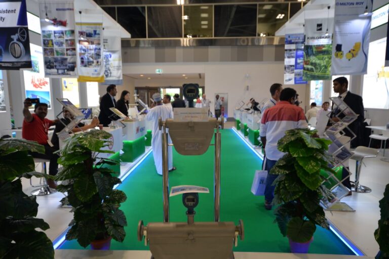
Coriolis flow meters are not necessarily the best choice for every application.
The correct technology depends on the process medium, required accuracy, operating conditions, installation environment, and budget.
| Flow Meter Type | Main Advantages | Main Limitations | Typical Applications |
|---|---|---|---|
| Coriolis | Direct mass measurement, high accuracy, density measurement | Higher cost, pressure drop, sensitivity to installation and multiphase conditions | Custody transfer, batching, chemical dosing |
| Vortex | Simple construction, suitable for steam and gases | Sensitive to vibration and low flow velocity | Steam, gases, general liquids |
| Electromagnetic | No moving parts, no obstruction, no significant pressure loss | Requires electrically conductive liquids | Water, wastewater, slurry |
| Differential Pressure | Mature technology, widely standardized | Requires pressure compensation for many gas and steam applications | Steam, gas, large pipelines |
| Ultrasonic | Clamp-on versions require no pipeline cutting | Performance depends on pipe condition, installation, and flow conditions | Water, large pipelines |
| Thermal Mass | Direct mass flow measurement for gases | Application suitability depends on gas composition and cleanliness | Compressed air, industrial gases |
When Should You Choose a Coriolis Flow Meter?
Consider Coriolis technology when:
- Direct mass flow measurement is required.
- High measurement accuracy is important.
- Fluid density must also be monitored.
- Accurate batching or dosing is necessary.
- The process involves valuable liquids or custody transfer.
For basic flow monitoring, alarms, or large water pipelines, electromagnetic, vortex, or ultrasonic flow meters may offer a more economical solution.
8. Final Commissioning Checklist
Before handing over a Coriolis mass flow meter, ask these questions:
Mechanical Installation
- Is the meter body free from excessive pipeline weight?
- Are the upstream and downstream supports properly installed?
- Are the flanges aligned without imposing unnecessary mechanical stress?
Process Conditions
- Are the measuring tubes completely filled?
- Has trapped gas been removed?
- Is the pump operating without cavitation?
- Is the fluid temperature stable?
Calibration and Configuration
- Was zero calibration performed under genuine zero-flow conditions?
- Is the zero offset consistent with the historical baseline?
- Are the URV, 20 mA output, and DCS scaling consistent?
- Is the low-flow cutoff configured appropriately?
Electrical and Communication
- Are grounding and shielding correctly installed?
- Is the HART communication loop configured according to the manufacturer’s requirements?
- Have diagnostic alarms been checked?
- Has any simulation or loop test mode been disabled before returning to normal operation?
Final Thoughts
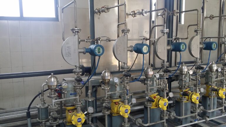
A Coriolis mass flow meter does not simply measure how much fluid passes through a pipeline. It measures the mechanical response of vibrating tubes to flowing fluid.
That is why seemingly minor installation problems can affect measurement performance.
In many cases, zero drift is not caused by a defective transmitter or sensor. It may result from pipeline stress, thermal expansion, trapped gas, internal deposits, or incorrect zero calibration.
Remember two fundamental requirements:
Keep the measuring tubes properly filled, and prevent unnecessary mechanical stress on the sensor.
When installation, process conditions, and zero calibration are properly controlled, a Coriolis mass flow meter can provide highly reliable mass flow, density, and temperature measurements for demanding industrial applications.
Recommended Applications: Chemical Processing | Oil & Gas | Custody Transfer | Food & Beverage | Batch Dosing | Petroleum Loading
Keywords: Coriolis Mass Flow Meter, Coriolis Flow Meter Zero Drift, Coriolis Flow Meter Troubleshooting, Zero Calibration, Mass Flow Measurement, Industrial Flow Meter