
An electromagnetic flow meter installed on a DN200 wastewater pipeline was consistently reading approximately 20% lower than the expected flow rate shown by the pumping system.
The maintenance team removed the meter and sent it for calibration. The meter passed inspection. They then replaced it with a new unit of the same model, but the reading remained low.
The actual problem was not the flow meter itself. The grounding connection was unreliable. After correcting the grounding connection and installing two grounding rings, the measurement returned to normal.
This type of problem is more common than many engineers realize.
Electromagnetic flow meters have no moving parts and can measure dirty water, wastewater, and slurry without creating significant pressure loss. However, their measurement signal is extremely small, typically in the millivolt range. Poor grounding, electrical interference, electrode contamination, or incorrect installation can therefore affect measurement stability and accuracy.
Before removing or replacing an electromagnetic flow meter, it is worth checking the grounding system.
This article explains the measurement principle, internal structure, grounding requirements, commissioning procedures, HART diagnostics, zero calibration, and practical troubleshooting methods.
1. How Does an Electromagnetic Flow Meter Work?
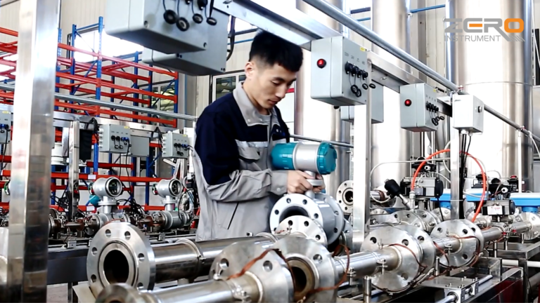
An electromagnetic flow meter operates according to Faraday’s law of electromagnetic induction.
When an electrically conductive liquid flows through a magnetic field, an electromotive force is generated across the liquid. Two electrodes installed on opposite sides of the measuring tube detect this voltage.
The induced voltage is proportional to the average flow velocity.
The basic relationship is:
E = B × D × v
Where:
- E = Induced voltage
- B = Magnetic flux density
- D = Internal diameter of the measuring tube
- v = Average flow velocity
The volumetric flow rate is calculated using:
Q = v × A
Where:
- Q = Volumetric flow rate
- v = Average flow velocity
- A = Cross-sectional area of the measuring tube
Because the measuring tube diameter is fixed, the induced voltage is proportional to the flow velocity and, consequently, the volumetric flow rate.
Why Is Excitation Technology Important?
Electromagnetic flow meters use excitation coils to generate a magnetic field.
Depending on the instrument design, different excitation technologies may be used, including:
- DC excitation
- AC excitation
- Pulsed DC excitation
- Dual-frequency excitation
Dual-frequency excitation is used in certain designs to improve zero stability and measurement performance under challenging flow conditions, including applications involving slurry and suspended solids.
However, excitation performance depends on the manufacturer’s specific design and signal-processing technology.
Minimum Conductivity Requirements
An electromagnetic flow meter can only measure electrically conductive liquids.
The minimum conductivity requirement varies according to the meter design and nominal diameter.
For example, the Yokogawa ADMAG TI AXG series specifies different conductivity limits for different diameter ranges. These values should be checked against the applicable product documentation before selection.
Typical applications include:
- Municipal wastewater
- Industrial process water
- Chemical liquids
- Slurry and pulp
- Irrigation water
- Acid and alkaline solutions
Applications involving oils, gases, and highly purified water generally require other measurement technologies unless the particular liquid meets the meter’s conductivity requirements.
Important: Conductivity alone does not guarantee accurate measurement. The liquid must also form a stable, continuous electrical connection between the measuring electrodes.
2. Understanding the Internal Structure
An electromagnetic flow meter mainly consists of six components.
2.1 Measuring Tube
The measuring tube provides the flow passage and supports the magnetic field arrangement.
It is normally constructed from a suitable non-magnetic material to avoid interfering with the magnetic field.
2.2 Lining
The lining electrically isolates the conductive liquid from the metal measuring tube.
Common lining materials include:
- PTFE
- PFA
- Rubber
- Polyurethane
- Ceramic
The correct lining depends on the liquid composition, temperature, pressure, abrasion resistance, and chemical compatibility.
A damaged, swollen, or detached lining may affect measurement performance.
2.3 Measuring Electrodes
The electrodes detect the induced voltage generated by the moving liquid.
Common electrode materials include:
- Stainless steel 316L
- Hastelloy C-276
- Titanium
- Tantalum
- Platinum-iridium
Electrode selection depends on the chemical properties of the medium.
Oil deposits, scaling, crystallization, or other contamination can affect electrode contact with the liquid and cause unstable or inaccurate readings.
2.4 Excitation Coils
The excitation coils generate the magnetic field inside the measuring tube.
Coil damage, moisture ingress, wiring faults, or insulation failure may trigger instrument diagnostics or prevent normal measurement.
2.5 Grounding Rings or Grounding Electrodes
Grounding components establish an appropriate electrical reference for the conductive liquid.
They are particularly important when measuring liquids in non-metallic pipes or electrically insulated pipelines.
2.6 Transmitter
The transmitter processes the small electrode signal and converts it into usable measurement outputs.
Common outputs include:
- 4–20 mA
- Pulse output
- RS485 / Modbus
- HART communication
- Local flow indication
The transmitter may be installed directly on the sensor or remotely through a dedicated signal cable.
3. Why Does Grounding Matter So Much?
The induced voltage detected by an electromagnetic flow meter is very small.
If the liquid does not have a stable electrical reference, external electrical interference may become significant compared with the useful measurement signal.
Typical symptoms include:
- Unstable flow readings
- Excessive measurement noise
- Zero-point drift
- Unexpected fluctuations when pumps start or stop
- Intermittent empty-pipe alarms
- Unreliable analog output
Grounding requirements depend on the pipeline material and installation arrangement.
Case A: Metal Pipelines
For conductive metal pipelines, the grounding arrangement should follow the flow meter manufacturer’s instructions.
The measuring tube, pipeline, and associated grounding system must have the appropriate electrical reference and equipotential bonding.
Where required, bonding connections should be installed across insulating joints or other electrically discontinuous sections.
Case B: Non-Metallic Pipelines
PVC, FRP, and other non-conductive pipelines cannot automatically provide the required electrical reference.
Grounding rings or grounding electrodes are commonly installed between the flow meter flanges and the pipeline.
They provide electrical contact with the liquid and establish the required reference potential.
Case C: Lined or Electrically Insulated Pipelines
Some pipelines have rubber, PTFE, or other insulating linings.
Even if the external pipe is metal, the liquid may be electrically isolated from the pipe wall.
In these installations, grounding rings or alternative grounding arrangements may be necessary.
Always check the manufacturer’s grounding diagram.
Important safety note: Instrument signal grounding, protective earthing, and equipotential bonding are related but different functions. Do not assume that connecting the flow meter housing to protective earth alone provides the correct liquid reference. Pipelines with cathodic protection or electrical isolation requirements also need special consideration. Never install bonding connections that compromise an engineered isolation system.
4. Correct Installation: Five Things to Check
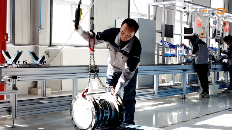
Even a high-quality electromagnetic flow meter may produce unreliable readings if installation conditions are incorrect.
4.1 Ensure the Measuring Tube Is Full
The measuring tube should remain completely filled with liquid during normal operation.
Avoid installation locations where air pockets can accumulate, especially at pipeline high points.
For horizontal pipelines, the electrode axis should normally be horizontal to reduce the risk of air or sediment affecting the electrodes.
4.2 Provide Adequate Straight Pipe Lengths
A common installation guideline is:
- Upstream straight length: 5D
- Downstream straight length: 3D
Here, D represents the nominal pipe diameter.
These are general guidelines, not universal requirements. Elbows, control valves, pumps, reducers, and other flow disturbances may require additional straight lengths depending on the meter design and manufacturer’s recommendations.
4.3 Check the Flow Direction
The arrow on the sensor body should match the intended process flow direction.
Some electromagnetic flow meters support bidirectional measurement, but the configuration and output settings must be checked.
4.4 Install Grounding Components Correctly
For installations requiring grounding rings:
- Ensure proper alignment with the measuring tube.
- Use suitable gaskets.
- Avoid obstructing the measuring passage.
- Confirm reliable electrical contact with the liquid.
- Follow the manufacturer’s grounding arrangement.
4.5 Check the Wiring and Shielding
For remote-type electromagnetic flow meters, inspect the excitation and electrode cables carefully.
Check for:
- Loose terminals
- Damaged cable insulation
- Moisture inside junction boxes
- Incorrect terminal connections
- Improper cable shielding
- Electromagnetic interference from nearby power cables or variable-frequency drives
Follow the manufacturer’s instructions for cable shielding and grounding. Avoid creating unintended ground loops.
5. Troubleshooting: Seven Checks Before Removing the Meter
When an electromagnetic flow meter reads lower than expected, follow a systematic inspection procedure.
Check 1: Is the Pipeline Completely Full?
An incompletely filled pipeline can cause incorrect readings or empty-pipe alarms.
Inspect the installation position, pump operation, air accumulation, and downstream pressure conditions.
Check 2: Is the Grounding System Correct?
Inspect the grounding wire, grounding rings, bonding connections, and electrical continuity.
Do not rely on the appearance of the grounding cable alone. Verify the electrical arrangement against the manufacturer’s requirements.
Check 3: Is the Liquid Conductivity Sufficient?
Check whether the actual liquid conductivity meets the minimum requirement of the flow meter.
Low conductivity may cause signal instability or measurement problems.
Check 4: Are the Electrodes Contaminated?
Inspect the electrodes for:
- Oil deposits
- Scale
- Crystallized material
- Biological deposits
- Chemical residue
Some advanced transmitters provide electrode coating or adhesion diagnostics. Where available, monitor the diagnostic trend to identify gradual electrode contamination.
Check 5: Is the Lining Damaged?
Inspect the lining for swelling, separation, abrasion, or mechanical damage.
A damaged lining can affect the electrical insulation and measurement performance.
Check 6: Are the Flow Range and Output Settings Correct?
Compare the transmitter settings with the DCS configuration.
Verify:
- Nominal diameter
- Flow unit
- Lower range value (LRV)
- Upper range value (URV)
- 4–20 mA scaling
- Damping
- Low-flow cutoff
- Flow direction
A mismatch between transmitter and DCS scaling can create the impression that the flow meter is reading incorrectly.
Check 7: Are There Electrical or Instrument Faults?
Inspect the excitation coil circuit, electrode wiring, transmitter power supply, and diagnostic alarms.
Where supported, use the transmitter’s built-in verification function before considering removal.
6. HART Diagnostics: What Should Engineers Look At?
For electromagnetic flow meters equipped with HART communication, a field communicator can provide useful diagnostic information.
The HART communicator should be connected according to the transmitter wiring diagram and the required loop-load conditions.
The following parameters are particularly useful.
Process Variable (PV)
Check the actual flow rate, flow velocity, and totalizer reading.
Compare these values with the local display and DCS.
Liquid Conductivity
Check whether the measured conductivity is stable and within the instrument’s operating range.
Unexpected changes may indicate a process condition or measurement issue.
Flow Noise
A sudden increase in flow noise may indicate:
- Poor grounding
- Air bubbles
- Pump-related interference
- Electrical interference
- Unstable process conditions
Electrode Adhesion Diagnostics
Some transmitter models provide an electrode adhesion or coating diagnostic parameter.
A gradual increase may indicate deposits accumulating on the electrodes.
This information can help maintenance teams schedule cleaning before the measurement becomes seriously affected.
Analog Output Verification
If the displayed flow rate is correct but the 4–20 mA signal is incorrect, perform a current-loop verification.
A D/A trim procedure can correct the analog output at 4 mA and 20 mA.
Remember that current-loop trimming only adjusts the analog output. It does not calibrate the actual flow measurement.
7. Zero Calibration and Flow Range Configuration
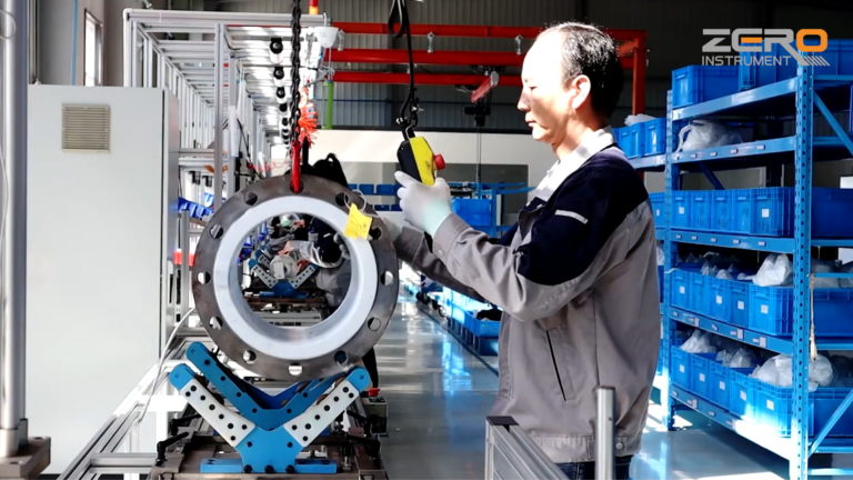
Zero calibration and range configuration are two different procedures.
Confusing them may introduce additional measurement errors.
7.1 Zero Calibration
Zero calibration should be performed under the following conditions:
- The measuring tube is completely full.
- The liquid is genuinely stationary.
- There is no leakage through the closed valve.
- The measurement signal is stable.
If liquid is still moving during zero calibration, the transmitter may incorrectly treat an actual flow signal as zero.
This can create a permanent measurement offset.
7.2 Flow Range Configuration
The upper range value (URV) should be selected according to the actual process operating range.
Do not automatically use the pump’s rated flow as the flow meter’s upper range value.
Consider:
- Normal operating flow
- Maximum expected flow
- Minimum operating flow
- Required accuracy
- Recommended velocity range
- Manufacturer’s permitted measuring range
For many liquid applications, a flow velocity around 3–4 m/s is a practical starting point, although the optimal value depends on the application.
7.3 Actual Flow Calibration
If measurement accuracy needs to be verified, use an appropriate reference method, such as:
- A calibrated reference flow meter
- A volumetric calibration system
- A gravimetric weighing system
Testing at multiple flow points helps evaluate measurement performance across the operating range.
A common test approach is to check approximately 20%, 50%, and 80% of the configured range, provided these points are within the reference system’s capability.
Changing the transmitter, sensor, or meter configuration does not automatically mean that a new flow calibration is always required. Check the sensor-transmitter compatibility, stored meter factor, calibration records, and manufacturer’s procedures.
8. Three Practical Troubleshooting Cases
Case 1: DN200 Wastewater Flow Meter Reads 20% Low
Symptoms:
The DCS flow reading was approximately 20% lower than expected.
The original meter passed calibration, and replacing it with a new unit did not solve the problem.
Investigation:
The maintenance team inspected the installation and found that the grounding arrangement was unreliable.
Corrective action:
The grounding connection was re-established, and two grounding rings were installed according to the required arrangement.
The reading returned to normal.
Lesson:
Do not assume that a low reading means the flow meter itself is defective. Grounding and electrical reference conditions should be checked first.
Case 2: Unstable Readings and Frequent Alarms
Symptoms:
The flow reading fluctuated continuously, generating numerous alarms during daily operation.
Investigation:
The flow meter was installed on a PVC pipeline without an appropriate grounding arrangement.
The liquid’s electrical reference was unstable during pump operation.
Corrective action:
Grounding rings and the required bonding connections were installed, and the grounding arrangement was connected to the designated grounding system.
The actual grounding performance was verified against the applicable installation requirements.
Lesson:
Non-metallic pipelines require particular attention to grounding and liquid reference potential.
Case 3: Frequent Empty-Pipe Alarms at the Pump Outlet
Symptoms:
The electromagnetic flow meter frequently reported an empty-pipe condition even though the pump was operating.
Investigation:
The meter was installed near the top of a vertical pipeline. Air bubbles accumulated around the measuring electrodes, and the pump also showed signs of cavitation.
Corrective action:
The installation arrangement was changed to a suitable horizontal pipe section, the electrode axis was positioned horizontally, and sufficient backpressure was maintained to reduce air accumulation.
The empty-pipe alarms were eliminated.
Lesson:
A full-pipe installation and suitable process conditions are essential for reliable electromagnetic flow measurement.
9. Electromagnetic Flow Meter vs. Other Flow Measurement Technologies
Electromagnetic flow meters are widely used, but they are not suitable for every application.
| Technology | Main Advantages | Main Limitations | Typical Applications |
|---|---|---|---|
| Electromagnetic | No moving parts, negligible pressure loss, suitable for dirty liquids | Requires conductive liquids and correct grounding | Water, wastewater, slurry |
| Coriolis | Direct mass flow measurement, high accuracy, density measurement | Higher cost, pressure drop, sensitivity to installation stress and gas conditions | Chemical dosing, custody transfer |
| Vortex | Simple construction, suitable for high temperatures and pressures | Sensitive to vibration and low flow velocity | Steam, gas, liquids |
| Differential Pressure | Established technology, suitable for high pressure and temperature | Permanent pressure loss and possible need for compensation | Steam, gas, large pipelines |
| Ultrasonic | Clamp-on installation available, no process interruption | Accuracy depends on pipe condition and flow profile | Water, large pipelines |
| Thermal Mass | Direct mass flow measurement for gases | Application-specific gas composition and cleanliness requirements | Compressed air, industrial gases |
The correct technology should be selected according to the medium, flow range, operating conditions, accuracy requirements, and installation environment.
10. Final Inspection Checklist
Before commissioning an electromagnetic flow meter or handing it over to the customer, check the following:
-
Is the liquid electrically conductive enough?
-
Is the measuring tube completely full?
-
Is the electrode axis correctly positioned?
-
Are the upstream and downstream straight lengths sufficient?
-
Is the flow direction correct?
-
Are grounding rings installed where required?
-
Are grounding and bonding connections correct?
-
Are the electrodes clean?
-
Is the lining in good condition?
-
Are the sensor and transmitter wiring correct?
-
Do the URV, 4–20 mA output, and DCS scaling match?
-
Has zero calibration been performed under genuine zero-flow conditions?
Final Thoughts
An electromagnetic flow meter is a reliable instrument when properly selected, installed, grounded, and maintained.
However, its measurement signal is relatively small, making it sensitive to electrical interference, grounding problems, electrode contamination, and incorrect installation.
When the reading becomes unusually low or unstable, replacing the meter should not be the first step.
Start with the process conditions. Check whether the pipe is full, verify the grounding arrangement, inspect the electrodes, and confirm the transmitter settings.
Sometimes, the problem is not inside the flow meter. It is in the grounding connection that everyone overlooked.