
Over the past few years, 80 GHz radar level transmitters have become increasingly popular in industrial level measurement. Manufacturers frequently highlight their narrow beam angles, excellent signal focusing, high measurement accuracy, and ability to operate in challenging environments.
As a result, some engineers automatically select 80 GHz radar for new projects, assuming that a higher operating frequency must deliver better performance.
But is 80 GHz always the better choice?
Not necessarily.
Although 80 GHz radar offers significant advantages in many applications, 26 GHz radar remains a practical and reliable solution for numerous liquid and bulk-solid measurement tasks.
The most suitable radar level transmitter depends not only on operating frequency but also on antenna design, dielectric constant, vapor conditions, foam, dust, tank geometry, and installation requirements.
This article explains the engineering differences between 80 GHz and 26 GHz radar level transmitters, identifies their advantages and limitations, and provides practical recommendations for selecting the right technology.
1. Understanding Radar Frequency and Beam Angle
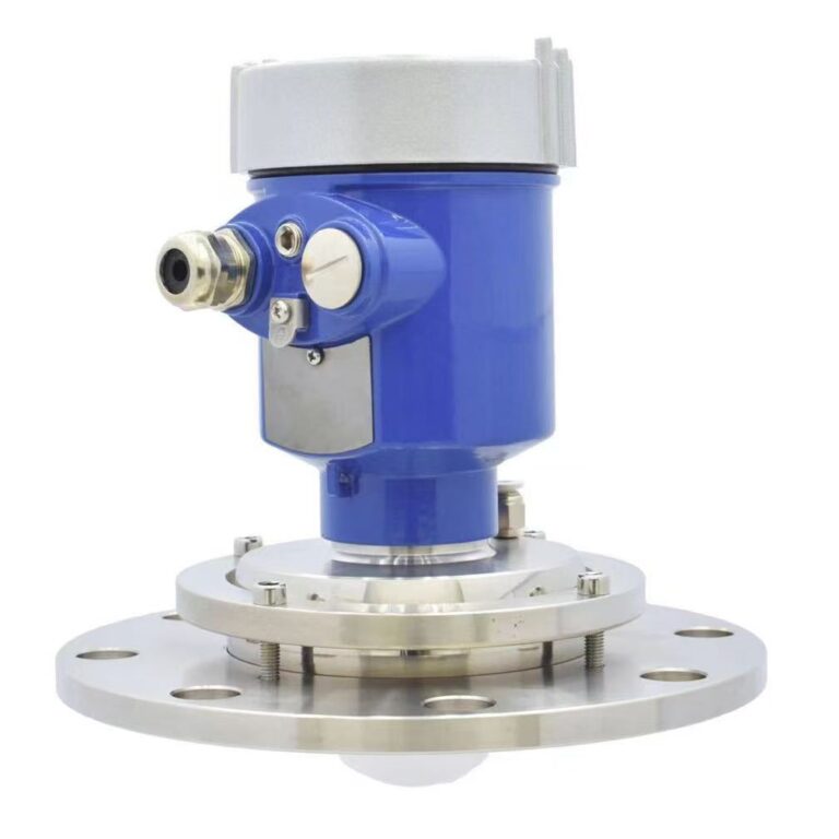
Radar level transmitters use electromagnetic waves to determine the distance between the sensor and the surface of a liquid or solid material.
The transmitted signal travels toward the product surface, where part of its energy is reflected toward the antenna.
The instrument processes the returned signal to determine the distance to the material surface and calculate the level.
Many modern radar level transmitters use Frequency-Modulated Continuous Wave (FMCW) technology, in which the instrument continuously changes the transmitted frequency over a defined bandwidth. The frequency difference between transmitted and received signals is used to calculate distance.
Two commonly used operating frequencies are:
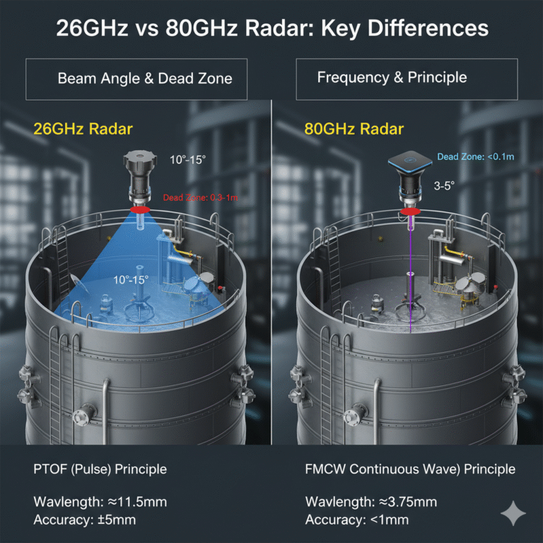
- 26 GHz radar: A well-established technology widely used in liquid tanks, storage vessels, and bulk-solid applications.
- 80 GHz radar: A higher-frequency technology that can achieve narrow beam angles with relatively compact antennas.
What Is Radar Beam Angle?
A radar antenna does not emit an infinitely thin signal. Instead, its electromagnetic energy spreads outward within a beam.
The beam angle describes the angular width of the antenna’s main radiation pattern, normally defined using the half-power (-3 dB) points.
A smaller beam angle concentrates more energy in a narrower direction, while a larger beam angle illuminates a wider area.
For an equivalent antenna aperture, higher-frequency radar generally produces a narrower beam.
However, beam angle is not determined by frequency alone. Antenna diameter, antenna type, and mechanical design also play important roles.
For example, one 80 GHz radar transmitter may have a beam angle of approximately 3°, while another model may have a wider beam depending on its antenna configuration.
Therefore, engineers should compare the actual antenna specifications rather than assume that every 80 GHz instrument has the same beam angle.
Why Does Beam Angle Matter?
Consider a radar transmitter installed on top of a storage tank containing internal pipes, heating coils, or structural supports.
A wide radar beam may illuminate these objects as well as the product surface.
The reflected signals can create competing echoes, making it more difficult for the transmitter to identify the correct level.
A narrower beam can reduce unwanted reflections by focusing more directly on the intended measurement area.
This is one of the most important practical advantages of 80 GHz radar technology.
2. Four Key Advantages of 80 GHz Radar Level Transmitters
2.1 Better Performance in Tanks with Internal Obstructions
Industrial storage tanks and processing vessels often contain internal structures such as:
- Agitator shafts and mixing blades
- Heating coils
- Internal piping
- Support brackets
- Reinforcement structures
These components can produce unwanted radar reflections.
When a transmitter receives multiple echoes, its signal-processing system must distinguish the actual product surface from surrounding objects.
The narrow beam available with many 80 GHz radar transmitters can reduce the number and strength of unwanted echoes.
Typical application: A chemical mixing tank containing an agitator and internal heating coils.
An appropriately positioned 80 GHz transmitter can direct most of its measuring energy toward an unobstructed portion of the liquid surface.
This can improve echo discrimination and measurement stability.
However, a narrow beam does not eliminate all interference. Moving agitator blades, unstable surfaces, and unsuitable installation positions may still require careful configuration or echo mapping.
2.2 Compact Antennas for Small Process Connections
Many industrial vessels have limited space for installing level measurement instruments.
Small tanks, compact reactors, and process vessels may have process connections such as DN40 or DN50.
Some 26 GHz radar transmitters use relatively large horn antennas, which can create mechanical limitations in small mounting connections.
Modern 80 GHz radar transmitters often use compact lens antennas, making them attractive for installations with limited space.
Nevertheless, small process connections should not automatically be considered suitable for every 80 GHz instrument.
Engineers must verify:
- Minimum process connection size
- Nozzle diameter and length
- Antenna position relative to the nozzle
- Risk of reflections from the nozzle wall
- Process temperature and pressure requirements
Engineering tip: A compact antenna does not necessarily mean the instrument can operate through any long or narrow nozzle.
Nozzle geometry should always be checked against the manufacturer’s installation recommendations.
2.3 Improved Measurement in Bulk-Solid Silos
Bulk-solid level measurement is frequently more complicated than liquid level measurement.
Materials such as cement, fly ash, lime powder, grain, and plastic pellets do not always form a flat surface.
During filling and discharge, they may create cones, sloping surfaces, or irregular material profiles.
These changing surface geometries can affect the radar echo.
A focused 80 GHz beam can help reduce reflections from silo walls and internal structures, particularly in tall and narrow vessels.
This makes 80 GHz radar especially attractive for applications such as:
- Cement storage silos
- Fly ash silos
- Mineral powder storage
- Grain storage facilities
- Plastic granule hoppers
- Chemical powder vessels
However, the radar still measures distance to the surface within its effective measuring area.
It does not automatically determine the average material level or total stored volume.
For irregular bulk-solid surfaces, the mounting position should be selected according to filling patterns, discharge points, and the required measurement objective.
In some applications, an aiming device or adjustable mounting bracket may be necessary.
2.4 Short Minimum Measuring Distances and High Resolution
Certain modern 80 GHz radar transmitters are designed for short minimum measuring distances.
This is particularly useful for compact tanks where the liquid surface may approach the sensor at high fill levels.
However, the minimum measuring distance is a product-specific parameter.
It depends on factors such as antenna design, signal-processing capability, internal reflections, and the transmitter’s measurement architecture.
A smaller beam angle alone does not guarantee a smaller minimum measuring distance.
Similarly, 80 GHz operation does not automatically guarantee superior measurement accuracy.
When comparing instruments, engineers should check the specified accuracy, resolution, repeatability, and minimum measuring distance independently.
3. Where 26 GHz Radar Still Makes Sense
Despite the advantages of 80 GHz radar, there are many situations where 26 GHz technology remains suitable.
3.1 Conventional Liquid Storage Tanks
For a large storage tank containing water or another liquid with a relatively stable surface, an 80 GHz transmitter may provide little practical improvement over a properly selected 26 GHz model.
If the vessel has:
- Few internal obstructions
- A suitable mounting position
- A stable liquid surface
- Adequate signal reflection
- Moderate measurement accuracy requirements
a 26 GHz radar transmitter may perform reliably at a competitive cost.
The actual project economics depend on the instrument model, required approvals, mounting accessories, and maintenance requirements.
3.2 Applications with Turbulent or Agitated Surfaces
Highly turbulent liquid surfaces can produce complex reflections.
Waves, splashing, and changing surface angles affect the direction and strength of the returned signal.
In some applications, the broader measurement area of a 26 GHz antenna may provide a useful response to surface movement.
However, this does not mean that 26 GHz radar is inherently more stable under turbulent conditions.
Modern 80 GHz instruments may also perform very well when equipped with suitable signal processing, high receiver sensitivity, and effective echo-tracking algorithms.
The correct selection depends on the actual application and should ideally be supported by manufacturer recommendations or field testing.
3.3 Existing Installations and Retrofit Projects
When replacing an existing radar level transmitter, engineering requirements may favor retaining a proven 26 GHz configuration.
For example, an existing instrument may already have:
- A suitable process connection
- A validated installation position
- Established PLC or DCS integration
- Approved hazardous-area documentation
- Reliable operating history
Changing to an 80 GHz instrument may require a review of mounting geometry, process compatibility, and instrument configuration.
Where an existing 26 GHz installation performs satisfactorily, upgrading solely to obtain a higher operating frequency may not provide meaningful benefits.
4. Radar Performance in Foam, Vapor, Condensation, and Dust
This is one of the most frequently misunderstood aspects of radar level measurement.
Higher operating frequency does not automatically make a radar sensor better or worse under every difficult process condition.
Different disturbances affect electromagnetic signals in different ways.
4.1 Foam: Frequency Is Only Part of the Problem
Foam is common in wastewater treatment plants, chemical reactors, fermentation tanks, and mixing processes.
Depending on its thickness, density, moisture content, and bubble structure, foam may reflect, absorb, or attenuate the radar signal.
In some situations, the radar detects the foam surface rather than the underlying liquid surface.
Higher-frequency radar signals can be more strongly attenuated by certain foam structures.
For this reason, a 26 GHz radar may offer an advantage in some foam-covered applications.
However, it would be incorrect to conclude that 80 GHz radar cannot measure through foam.
Modern 80 GHz transmitters with high dynamic range and advanced echo processing can detect weak signals returning through some foam layers.
Practical recommendation:
Before selecting a radar transmitter for a foaming application, determine whether the required measurement is the foam surface or the actual liquid surface.
Where thick, persistent foam is present, evaluate the instrument’s demonstrated performance under comparable conditions.
Guided wave radar, hydrostatic pressure measurement, or another level measurement principle may be more appropriate in certain applications.
4.2 Vapor and Condensation: Evaluate the Actual Process
High-temperature vessels, chemical reactors, and steam-containing environments introduce additional measurement challenges.
The severity of these challenges depends on:
- Vapor composition and density
- Operating temperature and pressure
- Condensation on the antenna
- Process connection geometry
- Signal attenuation and propagation characteristics
Some lower-frequency radar systems may offer advantages under particular vapor or condensation conditions.
Nevertheless, modern 80 GHz radar transmitters can operate successfully in many vapor-containing environments.
It is important to distinguish between vapor in the measurement path and liquid condensate accumulating on the antenna.
Condensation can create additional reflections or weaken the transmitted and received signals.
For demanding applications, specialized antennas, suitable process seals, or purge and cleaning arrangements may be required.
Engineering tip: Do not select 26 GHz or 80 GHz based solely on the presence of steam. Confirm the operating pressure, temperature, vapor composition, and condensation behavior first.
4.3 Heavy Dust in Cement and Powder Silos
Dust is a major concern in bulk-solid level measurement.
Cement, fly ash, and fine mineral powders can create dense airborne dust clouds during pneumatic filling or material transfer.
Radar measurement is generally less susceptible to airborne dust than ultrasonic measurement, but extremely demanding conditions may still reduce the usable radar signal.
The actual effect depends on particle properties, dust concentration, measuring distance, antenna design, and sensor sensitivity.
Modern 80 GHz radar transmitters with high dynamic range are widely used in dusty silo applications.
Their narrow beams can help reduce unwanted reflections from silo walls, structural components, and material buildup.
However, dust accumulation directly on the antenna remains a separate concern.
Where deposits become severe, air purging or suitable antenna protection may be necessary.
Air purging primarily helps keep the antenna clean; it does not eliminate all attenuation caused by airborne dust throughout the vessel.
5. Why Dielectric Constant Matters More Than Many Engineers Realize
One important factor in radar level measurement is the dielectric constant of the product.
The dielectric constant, often expressed as relative permittivity (εr), influences the strength of the radar reflection.
For a simplified ideal interface, the normal-incidence power reflection coefficient can be expressed as:
R = [(√εr − 1) / (√εr + 1)]²
This relationship assumes a nonmagnetic medium with negligible losses and illustrates why materials with dielectric constants close to that of air produce weak reflections.
Water, for example, has a relatively high dielectric constant under ordinary conditions and generally produces a strong radar echo.
Many hydrocarbons and plastic materials have much lower dielectric constants, producing weaker reflections.
For low-dielectric-constant products, the radar transmitter may require greater sensitivity and better echo discrimination.
This is particularly important for:
- Hydrocarbon liquids
- Organic solvents
- Plastic pellets
- Certain dry powders
- Light bulk solids
A high-quality 80 GHz transmitter with excellent receiver performance may outperform a less sensitive 26 GHz transmitter.
The opposite may also occur if the antenna, measuring range, or process conditions favor the lower-frequency instrument.
The key point is that frequency alone does not determine measurement reliability.
6. Dynamic Range: A Critical Factor in Radar Performance
Dynamic range is another important parameter that is sometimes overlooked during instrument selection.
In practical terms, it describes the range of signal strengths the radar system can handle and distinguish.
A high dynamic range can be particularly valuable when the return echo is weak.
This may occur when measuring:
- Low-dielectric-constant products
- Long measuring distances
- Foam-covered liquid surfaces
- Irregular solid materials
- Applications with significant signal attenuation
For example, two radar transmitters may operate at the same frequency but have substantially different receiver sensitivity and dynamic range.
One instrument may successfully identify a weak reflection that the other cannot reliably distinguish from noise or interference.
Advanced echo processing, antenna gain, and installation quality also contribute to overall performance.
Therefore, when comparing 26 GHz and 80 GHz radar transmitters, engineers should evaluate the complete measuring system rather than the operating frequency alone.
7. Does 80 GHz Radar Always Provide Better Accuracy?
Another common assumption is that higher-frequency radar automatically provides higher measurement accuracy.
This is not necessarily correct.
For FMCW radar, distance resolution is strongly related to the transmitted frequency sweep bandwidth.
In an idealized system, the distance resolution can be approximated by:
ΔR = c / (2B)
Where:
- ΔR = distance resolution
- c = speed of light
- B = transmitted frequency sweep bandwidth
This relationship demonstrates why the operating center frequency alone does not determine radar resolution.
It is also important to distinguish between distance resolution and measurement accuracy.
Actual measurement accuracy depends on calibration, signal quality, processing algorithms, mechanical reference stability, and installation conditions.
An 80 GHz transmitter may offer excellent accuracy, but its performance must be confirmed through its technical specifications.
Similarly, a properly installed 26 GHz radar may meet the accuracy requirements of many industrial processes.
For inventory monitoring, process control, and high-accuracy tank gauging, the required measurement uncertainty should be specified before selecting an instrument.
8. Practical Installation Considerations
Even a high-performance radar level transmitter may provide unreliable readings if installed incorrectly.
8.1 Avoid Unnecessary Obstructions
Install the radar where its measurement beam has a clear path to the product surface.
Avoid direct alignment with internal ladders, pipes, agitators, or other structures whenever possible.
For a radar with a narrow beam, the approximate beam footprint can be estimated using:
D = 2H × tan(θ/2)
Where:
- D = approximate beam diameter
- H = distance from the antenna to the target surface
- θ = radar beam angle
For example, a radar transmitter with a 4° beam angle installed 10 meters above the product surface produces an approximate main-beam diameter of 0.70 meters at that distance.
This geometric approximation is useful during preliminary installation planning.
However, the nominal beam boundary does not represent a sharp cutoff in radar energy. Significant reflections can still originate outside the calculated main beam.
8.2 Check Nozzle Geometry
Long or narrow mounting nozzles can create unwanted reflections.
The antenna position, nozzle diameter, and nozzle length should be verified against the manufacturer’s specifications.
This is particularly important when installing compact radar sensors on existing vessels.
8.3 Consider Filling and Discharge Points
For bulk-solid silos, avoid aiming the radar directly into the incoming material stream unless the application specifically requires it.
Material movement can create unstable echoes and measurement fluctuations.
The best mounting position should consider the expected shape of the material surface during both filling and discharge.
8.4 Use Appropriate Signal Filtering
Modern radar level transmitters often provide echo mapping, damping, and tracking functions.
These features can improve measurement stability, especially in tanks with internal obstructions or changing product surfaces.
However, excessive damping may delay the transmitter’s response to genuine level changes.
Signal filtering should therefore be configured according to the process dynamics and control requirements.
9. 80 GHz vs. 26 GHz Radar: Engineering Selection Guide
The following table summarizes practical selection considerations.
| Application | Recommended Approach |
|---|---|
| Tank with internal pipes or agitators | Often favor narrow-beam 80 GHz radar |
| Small process connection | Consider compact 80 GHz antenna designs |
| Cement or fly ash silo | Evaluate 80 GHz with suitable dynamic range |
| Conventional water storage tank | Both 26 GHz and 80 GHz may be suitable |
| Heavy foam | Evaluate foam behavior and demonstrated radar performance |
| High-temperature vapor environment | Check vapor effects, condensation, and process ratings |
| Highly turbulent liquid surface | Compare echo stability and signal processing |
| Low-dielectric-constant material | Prioritize receiver sensitivity and adequate echo margin |
| Existing 26 GHz installation | Retain if performance and requirements are satisfactory |
| High-accuracy inventory measurement | Select according to certified or specified accuracy |
Important: This table provides general engineering guidance, not universal selection rules.
Final selection should always be based on the specific instrument and application.
10. Common Mistakes When Selecting Radar Level Transmitters
Mistake 1: Assuming 80 GHz Is Always Better
Higher frequency provides advantages in certain applications, particularly where narrow beam focusing is beneficial.
However, it does not guarantee better performance under every process condition.
Mistake 2: Selecting by Beam Angle Alone
A narrow beam helps reduce unwanted reflections but cannot compensate for poor receiver sensitivity, unsuitable antenna design, or incorrect installation.
Mistake 3: Ignoring Product Dielectric Constant
Low-dielectric-constant materials produce weaker reflections and may require more sensitive radar instruments.
Mistake 4: Assuming Radar Is Completely Unaffected by Foam or Dust
Radar technology is highly capable in challenging industrial environments, but severe foam, dust, and antenna contamination can still affect measurement reliability.
Mistake 5: Confusing Small Measurement Dead Zones with Bottom-Level Performance
For a top-mounted radar, minimum measuring distance usually concerns the region nearest the antenna.
It should not be confused with the instrument’s ability to measure low product levels near the tank bottom.
Bottom-level measurement can also be influenced by tank geometry, weak reflections, and multiple echoes.
Mistake 6: Ignoring Process and Installation Compatibility
The operating frequency is only one part of instrument selection.
Engineers must also verify:
- Process pressure and temperature
- Wetted material compatibility
- Antenna material and process seal
- Hazardous-area approvals where required
- Measurement range and accuracy
- Output signals and communication protocols
- Mounting dimensions and installation restrictions
A radar transmitter that looks suitable on paper may still be inappropriate if its mechanical or environmental ratings do not match the application.
11. Final Recommendations: Choose the Technology That Fits the Process
The debate between 80 GHz and 26 GHz radar level transmitters should not be reduced to a simple comparison of operating frequencies.
80 GHz radar is often an excellent choice when:
- Narrow beam focusing is required.
- Internal obstacles create unwanted echoes.
- Compact process connections are necessary.
- Bulk-solid silos have challenging geometry.
- High-performance echo detection is needed.
26 GHz radar remains a reasonable choice when:
- Conventional liquid level measurement requirements are already satisfied.
- Existing installations have demonstrated reliable performance.
- A suitable antenna and mounting arrangement are available.
- Particular process conditions favor the selected lower-frequency radar design.
- Overall project cost and compatibility are important considerations.
For demanding applications involving heavy foam, vapor, condensation, or extreme dust, neither frequency should be selected without reviewing the actual process conditions.
In some situations, a different operating frequency or an alternative measurement technology may be more suitable.
Ultimately, the best radar level transmitter is not necessarily the one with the highest frequency or narrowest beam. It is the one that provides reliable, repeatable measurement under the actual operating conditions.
At Dalian Zero Instrument Technology Co., Ltd., we support industrial customers in selecting radar level measurement solutions for water treatment, chemical processing, storage tanks, and bulk-solid applications.
If you are evaluating a 26 GHz or 80 GHz radar level transmitter for your project, sharing the vessel dimensions, medium properties, process conditions, and installation details will help identify a suitable configuration.
Selecting the correct instrument from the beginning can improve measurement reliability, reduce commissioning difficulties, and minimize long-term maintenance requirements.