
Introduction
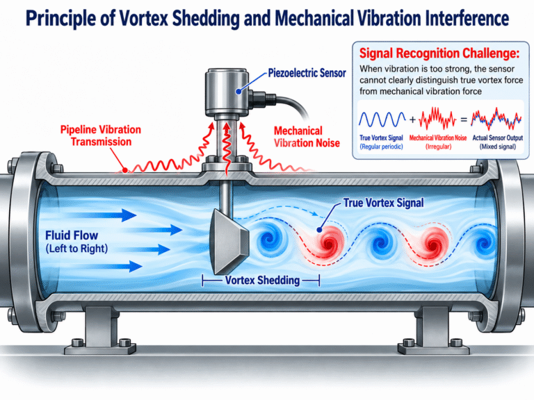
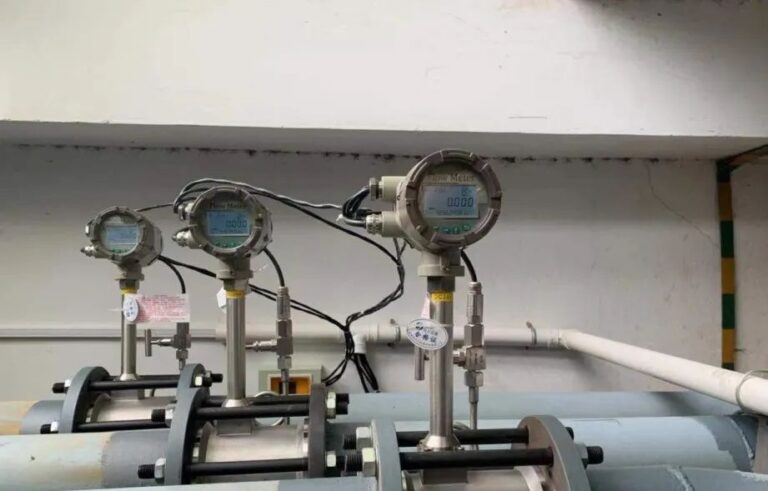
Vortex flow meters are widely used in industrial applications to measure the flow of liquids, gases, and steam. Their simple mechanical structure, lack of moving parts, and suitability for various process conditions make them a popular choice in power generation, chemical processing, compressed air systems, and steam distribution networks.
However, one common problem often occurs during operation:
Why does a vortex flow meter measure accurately at normal or high flow rates but become unstable, inaccurate, or even display zero at low flow rates?
Some operators suspect sensor damage. Others attempt to solve the problem by adjusting the K-factor, increasing sensitivity, or reducing the low-flow cutoff setting.
Although these adjustments may change the displayed reading, they do not necessarily address the underlying problem.
In many cases, poor low-flow performance is related to the physical characteristics of vortex shedding, the Reynolds number, signal detection limitations, or incorrect meter sizing.
Understanding these factors is essential for selecting, installing, and troubleshooting vortex flow meters.
1. Understanding the Vortex Shedding Principle
The operating principle of a vortex flow meter is based on a well-known fluid dynamics phenomenon called the von Kármán vortex street.
When fluid flows around a bluff body, alternating vortices can form downstream of the obstruction under suitable flow conditions.
These vortices are shed periodically from opposite sides of the body, creating an alternating pressure field.
A vortex flow meter uses a specially designed bluff body installed inside the measuring tube to generate this phenomenon.
A sensor detects the resulting periodic fluctuations and converts them into an electrical signal.
The frequency of vortex shedding is related to the velocity of the flowing fluid.
This relationship forms the basis of vortex flow measurement.
The Strouhal Number
The relationship between vortex shedding frequency and flow velocity is commonly expressed using the Strouhal number:
[
St=\frac{fb}{v}
]
Where:
- St = Strouhal number, dimensionless
- f = Vortex shedding frequency, Hz
- b = Characteristic width of the bluff body, m
- v = Flow velocity, m/s
Rearranging the equation:
[
f=\frac{St\cdot v}{b}
]
When the Strouhal number remains approximately constant for a particular bluff-body geometry and operating range, vortex shedding frequency is proportional to flow velocity.
Therefore:
Higher velocity produces a higher vortex shedding frequency, while lower velocity produces a lower frequency.
However, this proportional relationship is only sufficiently accurate when the instrument operates within its specified measurement conditions.
At low flow rates, several physical and electronic limitations can affect the relationship.
This is where low-flow measurement problems begin.
2. The Role of the K-Factor in Vortex Flow Measurement
In practical applications, vortex flow meters commonly use a calibration factor known as the K-factor.
The K-factor represents the number of detected pulses corresponding to a unit volume of fluid.
It is typically expressed in pulses per cubic meter or pulses per liter.
The volumetric flow rate can be calculated as:
[
Q_v=\frac{3600f}{K}
]
Where:
- Qv = Actual volumetric flow rate, m³/h
- f = Measured vortex shedding frequency, Hz
- K = Meter factor, pulses/m³
For example, if the detected frequency is 50 Hz and the calibrated K-factor is 1,000 pulses/m³:
[
Q_v=\frac{3600\times50}{1000}
]
[
Q_v=180\ \text{m}^3/\text{h}
]
This is an illustrative calculation, not a typical K-factor specification for every vortex flow meter.
The K-factor depends on the measuring tube, bluff-body geometry, calibration, and instrument design.
Is the K-Factor the Same as the Strouhal Number?
No.
Although they are related, they are not interchangeable.
The Strouhal number is a dimensionless fluid dynamics parameter, while the K-factor is an instrument calibration parameter with units of pulses per unit volume.
For an idealized meter geometry:
[
K=\frac{St}{bA}
]
Where A is the effective flow cross-sectional area.
This relationship assumes that the detected pulse frequency corresponds to the vortex shedding frequency and that the geometry and measurement conditions are appropriately defined.
In real instruments, the manufacturer determines the applicable K-factor through design characterization and calibration.
If the shedding characteristics change significantly outside the calibrated operating range, using a constant K-factor can introduce measurement errors.
This is one of the reasons vortex flow meters have defined minimum and maximum measurable flow rates.
3. Reynolds Number: A Key Factor in Low-Flow Performance
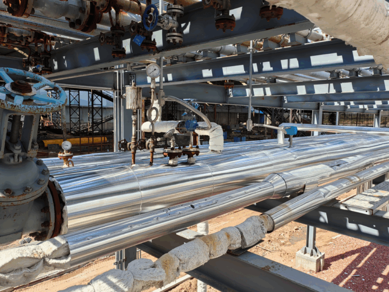
The Reynolds number is an important dimensionless parameter in fluid mechanics.
It describes the relationship between inertial and viscous forces within a flowing fluid.
For flow through a circular pipe:
[
Re=\frac{\rho vD}{\mu}
]
Alternatively:
[
Re=\frac{vD}{\nu}
]
Where:
- Re = Reynolds number
- ρ = Fluid density, kg/m³
- v = Average flow velocity, m/s
- D = Internal pipe diameter, m
- μ = Dynamic viscosity, Pa·s
- ν = Kinematic viscosity, m²/s
How Reynolds Number Affects Flow Behavior
In conventional pipe-flow analysis, the following ranges are commonly used as approximate references:
| Reynolds Number | General Pipe-Flow Regime |
|---|---|
| Re below approximately 2,300 | Laminar flow |
| Re approximately 2,300–4,000 | Transitional flow |
| Re above approximately 4,000 | Turbulent flow |
These values are approximate and depend on flow disturbances, inlet conditions, and other factors.
Importantly, the Reynolds number requirements of a vortex flow meter are not identical to the general criteria used to classify pipe flow as laminar or turbulent.
A vortex flow meter must generate a sufficiently stable vortex shedding pattern and detect it reliably.
Whether it can do so depends on the Reynolds number, bluff-body design, sensor technology, and signal processing system.
Why Low Flow Rates Cause Problems
For a given fluid and pipe diameter:
[
Re\propto v
]
As flow velocity decreases, the Reynolds number decreases.
At sufficiently low Reynolds numbers, the relationship between vortex shedding frequency and velocity may deviate from the instrument’s calibrated characteristics.
The Strouhal number may no longer remain sufficiently stable over the intended measurement range.
As a result, measurement accuracy can deteriorate.
In addition, the strength of the detected vortex signal may decrease, making reliable frequency identification more difficult.
These two mechanisms—changes in vortex shedding behavior and reduced signal detectability—are important contributors to poor low-flow performance.
Is Re = 10,000 a Universal Minimum?
No.
A Reynolds number of 10,000 is sometimes used as a reference threshold in discussions of vortex flow meter performance, but it should not be treated as a universal limit.
Different manufacturers and meter designs may specify different operating Reynolds number ranges.
Some instruments can operate at relatively low Reynolds numbers, while others require higher values to achieve their stated accuracy.
The correct minimum Reynolds number or minimum flow rate must be taken from the manufacturer’s technical documentation.
4. Five Main Reasons Vortex Flow Meters Become Inaccurate at Low Flow Rates
4.1 Weak Vortex Shedding Signals
One of the most important challenges at low flow rates is reduced signal strength.
As fluid velocity decreases, vortex-induced pressure fluctuations can become weaker.
Depending on the sensor design, the resulting electrical signal may approach the background noise level.
The sensor may then struggle to distinguish genuine vortex shedding from vibration or electrical interference.
Possible symptoms include:
- Flow readings intermittently dropping to zero
- Unstable instantaneous flow readings
- Missing or irregular frequency pulses
- Readings fluctuating despite relatively steady process conditions
Modern digital signal processing can improve signal detection, but it cannot guarantee reliable measurement below the instrument’s physical operating limits.
4.2 Reynolds Number Outside the Specified Range
As explained earlier, a lower flow velocity produces a lower Reynolds number.
If the Reynolds number falls outside the calibrated operating range, the vortex shedding characteristics may change.
In particular, the relationship between the Strouhal number and the Reynolds number may no longer be sufficiently stable.
This can produce systematic measurement errors.
However, a low Reynolds number does not automatically mean that vortex shedding stops completely.
The actual behavior depends on the bluff-body geometry and the instrument design.
The essential question is whether the instrument can maintain its specified measurement performance under the actual operating conditions.
4.3 Mechanical Vibration and Flow Pulsation
Vortex flow meters measure periodic signals.
Unfortunately, industrial piping systems can also generate periodic mechanical disturbances.
Common sources include:
- Centrifugal and reciprocating pumps
- Compressors
- Control valves
- Pipeline resonance
- Rotating machinery
- Pressure pulsations
At higher flow rates, the vortex shedding signal may be strong enough to be distinguished from these disturbances.
At lower flow rates, the useful signal becomes weaker, making interference more significant.
If the mechanical vibration frequency overlaps with the vortex shedding signal frequency, the transmitter may incorrectly identify the disturbance as a flow-related signal.
This can cause false readings, unstable measurements, or nonzero readings when the actual flow is very low.
4.4 Oversized Flow Meter
Incorrect meter sizing is a common engineering problem.
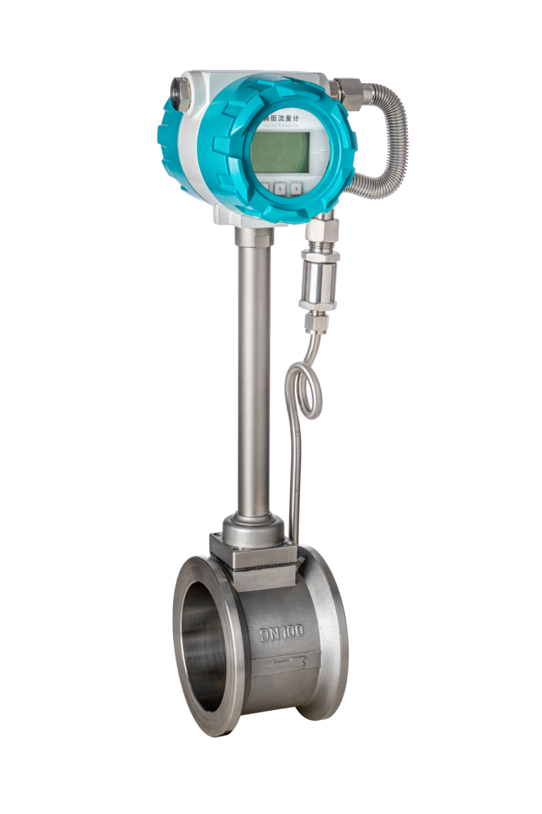
Consider a pipeline with a nominal diameter of DN100.
An engineer may automatically select a DN100 vortex flow meter because it matches the pipe size.
However, matching the pipe diameter does not guarantee correct flow measurement.
The actual minimum, normal, and maximum flow rates must be considered.
If the normal operating flow is relatively low, a full-bore DN100 meter may operate near or below its specified lower flow limit.
In this situation, a smaller measuring bore with suitable reducers may provide better low-flow performance.
However, downsizing must also account for:
- Maximum flow velocity
- Pressure loss
- Installation requirements
- Fluid properties
- Process safety limitations
- The manufacturer’s permitted flow range
The correct meter size should be based on the actual process conditions rather than pipe diameter alone.
4.5 Incorrect Low-Flow Cutoff and Signal Processing Settings
Many vortex flow transmitters include configurable parameters such as:
- Low-flow cutoff
- Damping time
- Signal sensitivity
- Noise rejection
- Frequency filtering
The low-flow cutoff function is designed to suppress unreliable or unwanted readings below a specified threshold.
For example, if a meter is configured with a low-flow cutoff of 5 m³/h, the transmitter may display zero whenever the calculated flow falls below this setting.
If the actual flow is 4 m³/h, the display may remain at zero even though fluid is moving through the pipeline.
This does not necessarily indicate sensor failure.
However, reducing the cutoff threshold does not automatically improve the underlying measurement accuracy.
It may simply allow unreliable low-frequency signals or noise to appear as measured flow.
A low-flow cutoff setting should never be used as a substitute for correct meter sizing and verification of the measurable flow range.
5. Understanding the Minimum Flow Rate and Accuracy Limits
Every vortex flow meter has a specified operating range.
A manufacturer’s datasheet may include:
- Minimum measurable flow rate
- Maximum measurable flow rate
- Reynolds number limitations
- Accuracy within specific operating ranges
- Repeatability
- Minimum measurable velocity
- Minimum fluid density requirements for gases and steam
These values must be evaluated together.
Why the 20% Flow Range Is Often Discussed
Some metrological accuracy classifications use a transitional flow rate to distinguish different permissible error ranges.
For example, the original article references the Chinese verification regulation JJG 1029-2007 and its flow-rate division at:
[
q_t=0.2q_{\max}
]
Where:
- qt = Transitional flow rate
- qmax = Maximum flow rate under the relevant classification
This distinction relates to the applicable metrological requirements and accuracy evaluation.
It should not be interpreted as a universal physical rule that vortex flow meters become inaccurate below exactly 20% of maximum flow.
Nor should the 20% boundary be assumed to correspond to a single Reynolds number for every installation.
Actual accuracy limits depend on the specific meter design, manufacturer’s specifications, and applicable calibration or verification requirements.
The current validity and applicability of any cited regulation should be checked before using it as a contractual or compliance reference.
6. Practical Example: Why an Oversized Meter May Fail at Low Flow
Consider a vortex flow meter installed in a water pipeline with the following simplified operating conditions:
| Parameter | Value |
|---|---|
| Pipe internal diameter | 100 mm (assumed) |
| Fluid | Water |
| Water temperature | Approximately 20°C |
| Actual volumetric flow | 2 m³/h |
| Kinematic viscosity | Approximately 1.0 × 10⁻⁶ m²/s |
First, calculate the cross-sectional area:
[
A=\frac{\pi D^2}{4}
]
[
A=\frac{\pi(0.1)^2}{4}=0.00785\ \text{m}^2
]
Convert the volumetric flow rate into cubic meters per second:
[
Q=\frac{2}{3600}=0.000556\ \text{m}^3/\text{s}
]
The average flow velocity is:
[
v=\frac{Q}{A}
]
[
v=\frac{0.000556}{0.00785}
]
[
v\approx0.071\ \text{m/s}
]
Now calculate the Reynolds number:
[
Re=\frac{vD}{\nu}
]
[
Re=\frac{0.071\times0.1}{1.0\times10^{-6}}
]
[
Re\approx7100
]
What Does This Result Mean?
The calculated pipe Reynolds number is approximately 7,100.
This is well above the commonly referenced turbulent-flow transition range, but it is still relatively low for some industrial vortex flow meter designs.
The meter may not achieve its specified accuracy at this operating point.
However, the Reynolds number alone is insufficient to conclude that the instrument will fail.
The next step is to check the manufacturer’s minimum liquid flow rate, applicable Reynolds number limits, K-factor characteristics, and accuracy specification.
If the operating flow is below the published measurement range, selecting a smaller measuring bore or a different measurement technology may be necessary.
This example illustrates an important principle:
A flow meter can be correctly installed and mechanically functional yet still be unsuitable for the actual operating flow range.
7. How to Troubleshoot Poor Low-Flow Measurement
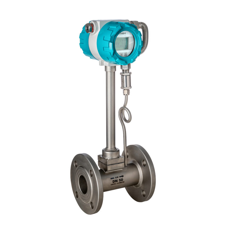
When a vortex flow meter becomes unstable at low flow rates, troubleshooting should follow a systematic sequence.
Step 1: Verify the Actual Operating Flow Range
Determine the minimum, normal, and maximum flow rates.
Compare these values against the manufacturer’s specified measurement range.
Do not rely solely on the nominal pipe diameter or the original design flow rate.
Step 2: Check Fluid Properties
Confirm the actual:
- Temperature
- Pressure
- Density
- Viscosity
- Fluid phase
For gases and steam, operating density can significantly affect the sensor’s minimum measurable flow.
A meter that operates satisfactorily at one pressure may perform differently at another pressure.
Viscosity is especially important when evaluating Reynolds number limitations.
Step 3: Inspect the Frequency Signal
Where the transmitter provides suitable diagnostics, examine the vortex frequency and signal quality.
Check whether the signal remains stable as the flow decreases.
Unstable frequency detection, weak signal amplitude, or excessive noise may indicate a low-flow limitation or external interference.
Step 4: Investigate Mechanical Vibration
Inspect nearby machinery and pipeline supports.
Pay particular attention to pumps, compressors, control valves, and vibrating sections of pipe.
If safe and practical, compare transmitter behavior under different machinery operating conditions.
Avoid changing process equipment operation without proper authorization.
Step 5: Review Transmitter Settings
Check the configured low-flow cutoff, damping, sensitivity, and filtering parameters.
Compare them with the manufacturer’s recommended settings.
Do not increase sensitivity indiscriminately, as excessive sensitivity may increase susceptibility to noise.
Step 6: Review Installation Conditions
Incorrect piping arrangements can introduce additional measurement errors.
Check:
- Upstream and downstream straight-run requirements
- Disturbances caused by elbows, reducers, and valves
- Flow profile asymmetry or swirl
- Whether liquid piping remains completely filled
- Whether gas or steam lines experience condensation or liquid accumulation
- Sensor installation orientation
Required straight-run distances vary by manufacturer and disturbance type. The applicable installation manual should always take precedence over generic recommendations.
Step 7: Reassess the Measuring Technology
If the required flow range extends below the vortex meter’s specified measurement capability, configuration adjustments may not solve the problem.
A different meter size or measurement technology may be more suitable.
8. How to Select a Vortex Flow Meter for Low-Flow Applications
The most effective way to prevent low-flow measurement problems is to address them during instrument selection.
Evaluate Minimum Flow Before Maximum Flow
Engineers often focus on maximum flow capacity.
However, the minimum operating flow is equally important.
Consider an application where the maximum flow is 100 m³/h, but the normal operating flow is only 15 m³/h and the minimum flow is 3 m³/h.
Selecting a meter solely because it accommodates 100 m³/h may result in poor performance during normal operation.
A suitable instrument must cover the required operating range while meeting the applicable accuracy, pressure loss, and process constraints.
Calculate Reynolds Number Under Actual Conditions
Use the minimum operating flow rate and the fluid properties at the relevant process temperature.
For liquids, viscosity may vary significantly with temperature.
For gases, operating pressure and temperature influence density, which affects the achievable Reynolds number and the strength of vortex-induced forces.
Calculations should therefore use actual process conditions rather than arbitrary reference values.
Confirm the Manufacturer’s Lower Measurement Limit
Datasheet specifications should always be checked.
Pay attention to whether the stated lower flow limit is based on:
- Reynolds number
- Minimum velocity
- Signal detectability
- Minimum operating density
- Specified measurement accuracy
The controlling limitation may vary with fluid type and operating conditions.
Consider Alternative Measurement Technologies
Vortex flow meters are not ideal for every low-flow application.
Depending on the fluid and process requirements, alternatives may include:
| Technology | Potential Advantage | Key Consideration |
|---|---|---|
| Electromagnetic flow meter | Suitable for low-velocity measurement of conductive liquids | Requires sufficient electrical conductivity |
| Coriolis mass flow meter | Direct mass flow measurement with strong low-flow capability in suitable models | Higher initial cost and application-specific pressure loss |
| Thermal mass flow meter | Useful for certain low-flow gas applications | Gas composition and calibration conditions matter |
| Positive displacement flow meter | Useful for some low-flow liquid applications | Moving parts and fluid cleanliness requirements |
| Ultrasonic flow meter | Nonintrusive options are available | Low-flow performance depends strongly on meter design and installation |
The optimal solution depends on the fluid, accuracy requirements, operating range, and overall project economics.
9. Frequently Asked Questions
Why does a vortex flow meter display zero when liquid is still flowing?
The actual flow may be below the minimum measurable flow rate or below the configured low-flow cutoff threshold.
Weak vortex signals, signal filtering, or installation problems may also contribute.
The meter’s diagnostic information and datasheet should be checked before changing settings.
Can increasing sensor sensitivity solve low-flow measurement problems?
Increasing sensitivity may help in some situations, but it can also make the transmitter more responsive to mechanical vibration and electrical noise.
Sensitivity adjustments should follow manufacturer recommendations.
They cannot extend the fundamental physical measurement range indefinitely.
Does a lower Reynolds number always produce a higher measurement error?
Not necessarily.
The relationship depends on the specific bluff-body design, calibration characteristics, and signal processing technology.
A low Reynolds number may affect vortex shedding characteristics, but the actual measurement error must be evaluated against the instrument’s specifications and calibration performance.
Can a vortex flow meter measure very low steam flow?
This depends on the meter design, steam density, operating pressure, temperature, and minimum specified flow.
At low steam flow rates, both vortex shedding characteristics and sensor signal strength may become limiting factors.
Steam applications also require consideration of condensate, wetness, and any temperature or pressure compensation used for mass flow calculations.
Will reducing the meter diameter improve low-flow accuracy?
A smaller measuring bore increases velocity at the same volumetric flow rate.
This may improve vortex signal detectability and extend the usable lower flow range.
However, downsizing increases velocity and may increase pressure loss.
The final selection must satisfy the entire operating range and the manufacturer’s installation and mechanical limitations.
10. Conclusion
Vortex flow meters do not become inaccurate at low flow rates for only one reason.
The problem can involve several interacting factors:
- Changes in vortex shedding characteristics at low Reynolds numbers.
- Reduced vortex-induced signal strength.
- Increased susceptibility to mechanical vibration and signal noise.
- Incorrect meter sizing and operation below the specified minimum flow.
- Inappropriate low-flow cutoff or signal processing settings.
Among these factors, Reynolds number is important, but it is not the only consideration.
A stable relationship between vortex shedding frequency and fluid velocity is essential, and the instrument must also detect the resulting signal reliably.
For engineers, the most important lesson is straightforward:
Never select a vortex flow meter based only on the pipeline diameter or maximum flow rate. Always verify the minimum operating flow, fluid properties, Reynolds number, and manufacturer’s specified measurement range.
When a vortex flow meter shows unstable or zero readings at low flow, the correct solution begins with understanding the process conditions—not simply adjusting the K-factor or lowering the cutoff setting.
Proper sizing, installation, and configuration remain the foundation of accurate and reliable vortex flow measurement.
About Zero Instrument
Zero Instrument provides industrial flow measurement solutions for liquids, gases, and steam, including vortex, electromagnetic, Coriolis, ultrasonic, and other flow measurement technologies.
For help selecting a suitable flow meter, visit www.zeroinstrument.com.
Technical note: Performance ranges, accuracy classifications, and minimum measurable flow rates vary by manufacturer and model. Always refer to the applicable product datasheet, calibration documentation, and operating instructions for final engineering decisions.