
In many storage tanks, the available space on the roof is limited, and the existing nozzle may be located very close to the tank wall.
It can therefore be tempting to install a radar level transmitter at this position.
After installation, the instrument may appear to work normally when the tank level is high. However, as the liquid level drops, the reading may begin to fluctuate, become unstable, or even suddenly jump to an incorrect value.
When this happens, one of the first things worth checking is the radar mounting position.
In many cases, the problem is related to three factors:
- Radar beam width
- Reflections from the tank wall
- Internal tank structures
Understanding how these factors interact can help prevent many radar level measurement problems before commissioning even begins.
1. Radar Does Not Travel as a Single Straight Line
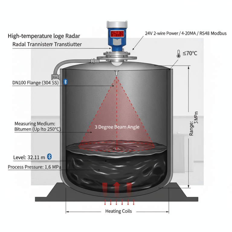
A non-contact radar level transmitter sends electromagnetic waves from its antenna toward the material surface.
When the signal reaches the liquid or solid surface, part of the energy is reflected back to the antenna. The instrument calculates the distance based on the travel time of the reflected signal and converts this into a level value.
However, the transmitted radar signal is not an infinitely narrow line.
It forms a beam with a certain beam angle.
As the distance from the antenna increases, the beam covers a progressively larger area.
If:
- H = distance from the antenna to the product surface
- θ = radar beam angle
- r = beam radius at the product surface
the approximate beam radius can be calculated as:
r = H × tan(θ / 2)
This equation tells us something very important:
The longer the measuring distance, the wider the radar beam becomes.
For example, suppose a radar has a beam angle of 8° and the distance from the antenna to the minimum liquid level is 10 m.
The beam radius is approximately:
r = 10 × tan(4°) ≈ 0.70 m
This means the beam diameter at that point is approximately 1.4 m.
Therefore, when selecting the installation position, it is not enough to consider only the area immediately below the antenna.
The entire beam path — from the antenna down to the minimum operating level — should be considered.
2. What Happens When the Beam Reaches the Tank Wall?
Inside a storage tank, the liquid surface is not the only object that reflects radar energy.
Other reflective surfaces may include:
- Tank walls
- Weld seams
- Reinforcing rings
- Heating coils
- Internal piping
- Ladders
- Support structures
- Agitators
Metal structures can produce especially strong reflections.
If the radar transmitter is installed too close to the tank wall, part of the radar beam may strike the wall instead of travelling directly toward the product surface.
The transmitter may then receive several different echoes at the same time:
- The actual product surface echo
- Tank wall reflections
- Reflections from internal structures
- Secondary or multiple reflections
As a result, the echo curve becomes more complicated.
If the product has a strong dielectric constant and the surface is calm, the instrument may still identify the correct level echo without difficulty.
However, if the application involves:
- Low-dielectric liquids
- Foam
- Vapour
- Condensation
- Agitation
- Turbulent surfaces
the useful level echo may become weaker or less stable.
At the same time, reflections from fixed metal structures may remain strong.
This can make it more difficult for the radar transmitter to determine which echo corresponds to the actual level.
These unwanted reflections are often referred to as false echoes or interference echoes.
3. Why Are Problems Often Worse at Low Level?
This is a very common field observation.
When the tank level is high, the distance between the radar antenna and the liquid surface is relatively short.
At this point, the radar beam is still narrow.
As the liquid level falls, the measuring distance increases and the beam becomes wider.
Eventually, the beam may begin to reach:
- The tank wall
- Heating coils
- Reinforcement structures
- Internal pipes
- Ladders
- Agitator components
Once these objects enter the radar beam, the echo pattern may change significantly.
This explains why some radar installations behave like this:
At high level, the reading is stable.
At medium or low level, the signal suddenly begins to fluctuate.
In some cases, the lower the level becomes, the worse the instability becomes.
When this pattern appears, the radar beam path should be checked carefully.
4. Multipath Reflections Can Also Cause Jumping Readings
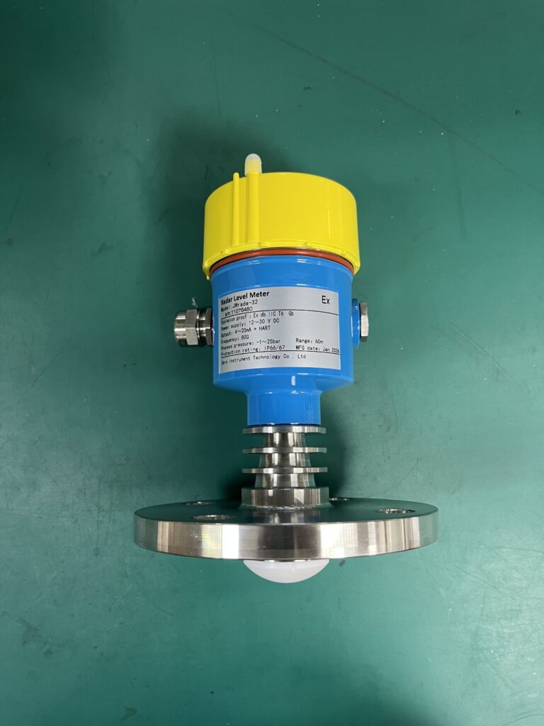
Radar signals do not always follow only one propagation path inside a tank.
Some energy travels directly to the liquid surface and returns to the antenna.
Other portions of the signal may:
- Hit the tank wall,
- Reflect toward the liquid surface,
- Reflect again toward another metal structure,
- And eventually return to the radar antenna.
Because these signals travel different distances, they return at different times.
The transmitter may therefore detect several echo peaks at different positions.
This phenomenon is known as multipath reflection.
As the liquid level changes, the geometry of these reflections also changes.
This can lead to a typical field symptom:
The level reading suddenly jumps within a certain level range, and then becomes stable again after the level moves beyond that range.
When measurement problems occur only at particular liquid levels, multipath reflection or interference from internal structures should be considered.
5. How Far Should a Radar Transmitter Be from the Tank Wall?
There is no single distance that is correct for every radar level transmitter.
In the field, people often mention rules such as:
- 300 mm from the tank wall
- 500 mm from the tank wall
- 1 m from the tank wall
These values may be useful as rough experience, but they should not be treated as universal installation requirements.
The correct mounting position depends on several factors.
5.1 Radar Beam Angle
A radar with a larger beam angle covers a wider area.
For the same measuring distance, a wide-beam radar requires more clear space between the beam and surrounding structures.
A narrow-beam radar can usually operate in a more restricted installation area.
5.2 Tank Height
The taller the tank, the longer the measuring distance at low level.
A longer distance means a larger beam footprint.
Therefore, the installation position on a 3 m tank may be acceptable while the same relative position on a 20 m tank may cause the radar beam to reach the tank wall.
Always consider the maximum measuring distance, not only the normal operating level.
5.3 Radar Frequency and Antenna Design
Radar frequency influences the achievable antenna size and beam characteristics, but frequency alone does not determine the final beam angle.
The actual beam width depends on factors such as:
- Operating frequency
- Antenna diameter
- Antenna type
- Antenna design
Modern high-frequency radar instruments can often achieve very narrow beam angles with relatively small antennas.
This is particularly useful when installation space is limited.
5.4 Internal Tank Structures
Before selecting the nozzle position, check what lies underneath it.
Potential interference sources include:
- Agitator shafts
- Agitator blades
- Heating coils
- Filling pipes
- Internal ladders
- Reinforcing structures
- Support beams
- Baffles
The cleaner the radar beam path, the easier it is for the transmitter to identify the true product surface.
A clean beam path usually means a cleaner echo curve and more stable level measurement.
6. Are 80 GHz Radar Level Transmitters Better for Tight Spaces?
In many applications, yes.
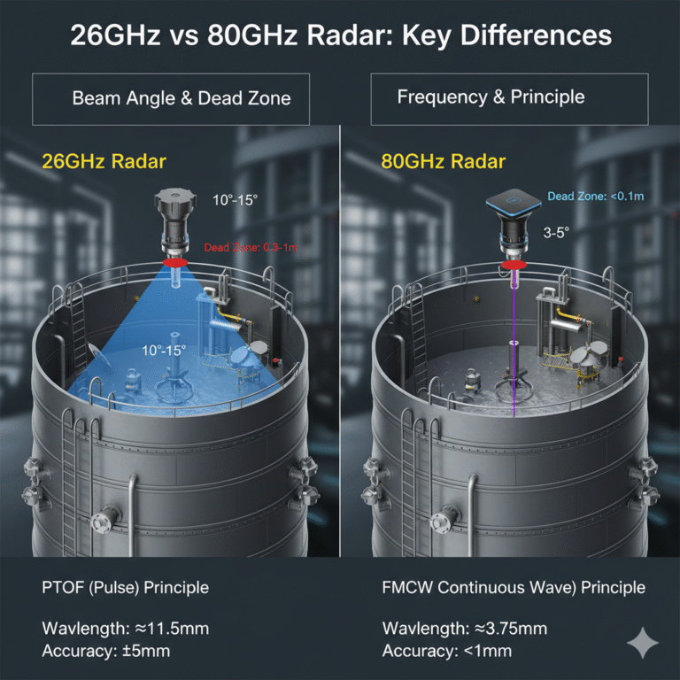
Modern 80 GHz radar level transmitters can often provide a relatively narrow and highly directional radar beam.
Compared with many traditional lower-frequency radar instruments, an 80 GHz radar can often achieve a narrower beam with a smaller antenna.
This makes it particularly useful for applications such as:
- Small storage tanks
- Narrow vessels
- Tanks with many internal structures
- Nozzles located close to the tank wall
- Tanks with agitators or heating coils
- Applications with limited mounting space
A narrower beam makes it easier to avoid unwanted reflections from surrounding structures.
However, it is important to remember that:
Not all 80 GHz radar transmitters have the same beam angle.
The actual beam width depends on the antenna size and design of the specific instrument.
Therefore, the manufacturer’s technical documentation should always be checked during selection.
Correct antenna orientation is also important.
The antenna should normally be aligned so that the main radar beam points toward the product surface without intersecting unnecessary obstacles.
7. Other Installation Positions That Should Be Avoided
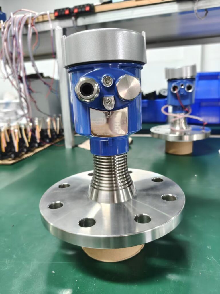
The tank wall is not the only source of radar interference.
Several other locations should also be considered carefully.
Near the Filling Inlet
When liquid enters the tank, it may create:
- Splashing
- Foam
- Turbulence
- Waves
In solids applications, the filling stream itself may pass through the radar beam.
If the filling stream enters the measurement path, the radar may temporarily detect the incoming material instead of the actual product surface.
Whenever possible, the radar should be installed away from the filling stream.
Near an Agitator
Rotating agitator blades continuously change position.
Because they are usually metallic, they can generate strong reflections that move periodically through the radar beam.
This may create repeating echo disturbances.
If possible, install the radar so that the main beam does not intersect the agitator blades.
Near Ladders, Heating Coils and Reinforcement Structures
These structures are often metallic and can produce strong fixed reflections.
The radar beam should pass through the most open section of the tank whenever possible.
On a Long or Narrow Nozzle
Radar transmitters are frequently installed on process nozzles.
However, nozzle dimensions are important.
If the nozzle is:
- Too long
- Too narrow
- Incorrectly matched to the antenna
the radar signal may reflect inside the nozzle before entering the tank.
This can create additional interference signals.
The antenna should be selected and positioned according to the manufacturer’s recommended nozzle dimensions.
8. The Instrument Is Already Installed — What Should You Check?
If the radar transmitter is already installed and the measurement is unstable, start by checking the echo curve.
Useful questions include:
- Where is the actual product surface echo?
- How strong is the product echo?
- Are there strong fixed interference peaks?
- Do these peaks change as the level rises or falls?
- Which echo is the instrument currently tracking?
- Does the unstable reading occur only within a certain level range?
The echo curve often provides much more information than simply watching the displayed level value.
9. Can False Echo Mapping Solve the Problem?
Many modern radar level transmitters provide functions such as:
- False echo suppression
- Interference echo mapping
- Echo learning
- Tank mapping
These functions can help the transmitter identify known reflections from fixed structures.
For example, a fixed ladder or reinforcement ring may create a stable echo at a known distance.
The radar can often learn this reflection and reduce its influence on the measurement.
However, one important principle should be remembered:
False echo mapping cannot replace correct mechanical installation.
Software functions are most effective against relatively stable, fixed interference echoes.
They are less effective when interference is caused by changing conditions such as:
- Moving agitator blades
- Filling streams
- Heavy foam
- Turbulent surfaces
- Dynamic multipath reflections
- Changing condensation conditions
Whenever possible, it is better to create a clean radar beam path mechanically than to depend entirely on signal processing.
10. A Better Way to Think About Radar Installation
Instead of asking:
“Should the radar be 300 mm or 500 mm away from the tank wall?”
a better engineering question is:
“At the minimum liquid level, where will the radar beam actually travel?”
Then check:
- How wide is the radar beam?
- Will the beam reach the tank wall?
- Are there ladders, coils or pipes inside the beam?
- Will the filling stream cross the beam?
- Will the agitator blades enter the measurement area?
- Is the nozzle suitable for the selected antenna?
Once these questions are answered, the correct mounting position usually becomes much clearer.
Conclusion
A non-contact radar level transmitter should be given the cleanest possible signal path from the antenna to the product surface.
If the transmitter is installed too close to the tank wall, part of the radar beam may strike the wall, welds, reinforcement structures or other metal objects.
As the level falls and the radar beam becomes wider, these objects may enter the beam and produce additional reflections.
The result can be:
- False echoes
- Multiple echo peaks
- Unstable readings
- Sudden level jumps
- Loss of echo tracking
For reliable radar level measurement, consider the complete beam path down to the minimum operating level.
Do not select the installation position based only on a fixed rule such as “300 mm from the wall.”
Instead, evaluate:
- Radar beam angle
- Maximum measuring distance
- Antenna design
- Tank dimensions
- Internal structures
- Nozzle dimensions
- Process conditions
And remember:
The cleaner the radar beam path, the easier it is for the transmitter to identify the true product level.
This discussion mainly applies to non-contact radar level transmitters.
Guided wave radar operates differently because the electromagnetic pulse travels along a probe or cable. Its installation requirements, interference mechanisms and measurement behaviour are therefore different from those of free-space radar.
For each application, the final installation should always be checked against the specific radar model, antenna type, process conditions and tank geometry.