
How entrained air, gas bubbles, cavitation, and changing flow patterns affect industrial flow measurement accuracy.
In an industrial liquid pipeline, the pump operates at a constant speed, the control valve remains in the same position, and the process appears stable. However, the flowmeter reading suddenly increases, drops, or fluctuates continuously.
The pressure transmitter may show similar fluctuations.
The first reaction is often to suspect a faulty instrument. Maintenance personnel check the wiring, power supply, transmitter configuration, sensor condition, and signal output. Everything appears normal, yet the measurements remain unstable.
In many cases, the real problem is not the instrument itself but a change in the physical condition of the flowing medium.
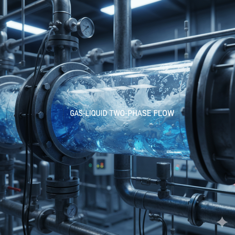
A pipeline designed to transport a single-phase liquid may begin carrying a mixture of liquid and gas. This condition, known as gas–liquid two-phase flow, can significantly affect pressure measurements, flowmeter performance, pump operation, and overall process stability.
Understanding how two-phase flow develops is essential for diagnosing unstable measurements and selecting appropriate flow measurement technology.
1. How Does Gas Enter a Liquid Pipeline?
Gas in a liquid pipeline does not necessarily indicate an equipment failure. It can originate from several different physical processes.
1.1 Air entrainment at the pump suction
One of the most common causes is air entering the pipeline through the pump suction system.
Consider a storage tank supplying liquid to a centrifugal pump. As the tank level decreases, a vortex may develop near the suction outlet.
If the liquid level becomes too low, the vortex can draw air from above the liquid surface into the suction pipe.
The pump then transports a mixture of liquid and air rather than a uniform liquid.
Typical symptoms include:
- Unstable discharge pressure.
- Fluctuating flowmeter readings.
- Increased pump noise or vibration.
- Reduced pumping efficiency.
- Irregular operation as the storage tank level decreases.
Air may also enter through poorly sealed suction connections.
When a pump operates with pressure below atmospheric pressure at its suction inlet, defective gaskets, loose flange connections, or improperly sealed fittings can allow outside air to enter.
Importantly, such connections may admit air without showing visible liquid leakage.
This makes suction-side air ingress particularly difficult to identify during routine inspections.
1.2 Gas released from the liquid
Not all gas enters from outside the pipeline.
Many industrial liquids contain dissolved gases. Depending on pressure, temperature, and liquid composition, these gases may remain dissolved under normal operating conditions.
When the pressure decreases or the temperature increases, some dissolved gas can come out of solution and form bubbles.
This phenomenon is known as gas breakout or gas evolution.
For example, a liquid containing dissolved air may release bubbles as it passes through a region of reduced pressure.
The pipeline can therefore develop two-phase flow even when all mechanical connections are properly sealed.
1.3 Vapor formation caused by pressure reduction
Another important mechanism is liquid vaporization.
When liquid passes through a control valve, orifice plate, restriction, or other flow resistance, its local static pressure may decrease significantly.
If the local pressure falls below the liquid’s saturation vapor pressure at the prevailing temperature, part of the liquid can vaporize.
Vapor bubbles then appear in the flowing medium.
Depending on the downstream pressure recovery, these vapor bubbles may subsequently collapse or remain in the flow.
This distinction is important when investigating cavitation and flashing.
1.4 Why the source of the gas matters
Although air entrainment, dissolved-gas release, and vaporization can all produce gas–liquid mixtures, they are not identical phenomena.
Entrained air originates outside the liquid system. Dissolved gas comes out of solution when process conditions change. Vapor bubbles form when the liquid undergoes a local phase change.
These mechanisms require different troubleshooting approaches.
For example, repairing a pump suction leak will not solve vaporization caused by excessive pressure reduction across a control valve.
Likewise, increasing downstream pressure may reduce vapor formation but will not necessarily eliminate air entering through a defective suction connection.
Correct diagnosis begins with identifying where the gas originates and why it appears.
2. Understanding Gas–Liquid Two-Phase Flow Patterns
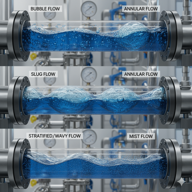
Once gas is present in a liquid pipeline, it does not always travel as small, uniformly distributed bubbles.
The distribution of gas and liquid depends on several factors, including:
- Gas and liquid flow rates.
- Pipe diameter and orientation.
- Fluid density, viscosity, and surface tension.
- Operating pressure and temperature.
- Pipeline geometry and changes in flow direction.
Different combinations of these parameters create different flow patterns, commonly called flow regimes.
2.1 Bubbly flow
In bubbly flow, relatively small gas bubbles are dispersed throughout the continuous liquid phase.
This often occurs when the gas content is relatively low.
The liquid remains the dominant phase, and bubbles are transported along with the flow.
However, even relatively small amounts of entrained gas may influence sensitive flow measurements.
The impact depends on bubble size, gas distribution, meter design, and operating conditions.
2.2 Slug flow
As gas accumulates or the flow conditions change, small bubbles may combine into larger gas pockets.
These gas pockets can form elongated structures separated by liquid-rich regions.
This flow pattern is commonly referred to as slug flow.
Slug flow is especially important in industrial measurement because alternating gas-rich and liquid-rich sections can produce significant fluctuations in local pressure, velocity, and density.
As a gas slug passes through a measuring section, the instrument experiences very different conditions from those encountered during the following liquid-rich section.
The result may be unstable flow readings, pressure fluctuations, and mechanical vibration.
In severe cases, slug flow can also impose substantial dynamic loads on piping and equipment.
2.3 Stratified flow
In horizontal pipelines, gas and liquid may separate under the influence of gravity.
The denser liquid occupies the lower part of the pipe, while the gas travels above it.
This is known as stratified flow.
Depending on the gas and liquid velocities, the interface between the two phases may be relatively smooth or develop waves.
Stratified flow is particularly problematic for instruments that assume a completely liquid-filled measurement section.
2.4 Annular flow
At sufficiently high gas velocities and suitable operating conditions, an annular flow pattern may develop.
In this regime, gas generally occupies the central region of the pipe, while liquid forms a film along the pipe wall.
Liquid droplets may also be entrained within the gas core.
Annular flow is more commonly associated with gas-dominated conditions and should not be interpreted as a universal consequence of increasing gas content.
2.5 Flow patterns can change during operation
One of the most challenging aspects of two-phase flow is that its structure can change over time.
A pipeline may initially operate with a small number of dispersed bubbles.
As the tank level decreases, suction pressure changes, or operating flow rates vary, the gas distribution may become less uniform.
Bubbly flow may transition into larger gas pockets or intermittent slug flow.
Consequently, an instrument that operates normally during startup may begin showing unstable readings later.
The instrument has not necessarily changed. The flow conditions inside the pipeline have changed.
This is why flow measurement problems should always be evaluated together with process operating conditions.
3. How Gas–Liquid Two-Phase Flow Affects Flowmeters
Different flowmeter technologies respond differently to entrained gas.
An instrument designed and calibrated for single-phase liquid measurement may not provide accurate results when gas and liquid flow together.
The magnitude and direction of the error depend on the measurement principle, gas volume fraction, flow pattern, and instrument design.
3.1 Electromagnetic flowmeters: entrained air and incomplete pipe filling
Electromagnetic flowmeters are widely used for measuring conductive liquids in applications such as water treatment, chemical processing, and industrial utilities.
Their operating principle is based on Faraday’s law of electromagnetic induction.
When a conductive liquid moves through a magnetic field, an electrical voltage is induced between the measuring electrodes.
Under the specified measurement conditions, this voltage is proportional to the average liquid velocity.
Electromagnetic flowmeters are generally designed to operate with a completely filled measuring tube.
What happens when gas enters the measuring tube?
Gas bubbles can disturb the conductive liquid distribution and local velocity field.
Depending on the gas concentration, bubble distribution, electrode conditions, and meter design, entrained gas can introduce measurement errors or unstable signals.
A particularly important distinction is that a pipe can remain physically full while containing a mixture of liquid and gas.
Under these circumstances, the electromagnetic flowmeter may still display a stable value, but that value should not automatically be interpreted as the true volumetric flow rate of the liquid phase.
Standard electromagnetic flowmeters do not independently determine the liquid and gas flow rates in a two-phase mixture.
If gas accumulates near the top of the measuring tube and the pipeline becomes partially filled, the measurement conditions deteriorate further.
Some electromagnetic flowmeters provide empty-pipe detection functions that may identify loss of liquid contact under suitable installation and operating conditions.
However, empty-pipe detection should not be considered a reliable quantitative measurement of entrained gas.
Practical troubleshooting recommendations
When an electromagnetic flowmeter shows unexplained fluctuations, check the following:
- Is the measuring tube completely filled under all operating conditions?
- Is the meter installed near a pipeline high point where gas can accumulate?
- Does the reading become unstable when the storage tank level decreases?
- Are air bubbles entering from the pump suction system?
- Does the instrument report an empty-pipe or electrode-related diagnostic alarm?
- Are the grounding, wiring, and electrical connections functioning correctly?
Where possible, select an installation location that maintains a completely filled measuring tube and minimizes gas accumulation.
For example, an upward-flowing vertical pipe section can be advantageous in many liquid applications because it helps transport bubbles through the measuring section rather than allowing them to accumulate.
However, the final installation arrangement should always follow the manufacturer’s instructions and the requirements of the process.
3.2 Differential pressure flowmeters: changing density and unstable differential pressure
Differential pressure flowmeters, including orifice-plate systems, determine flow rate from the pressure difference generated by a primary flow element.
For an incompressible single-phase liquid, the basic flow relationship can be expressed approximately as:
[
Q \propto \sqrt{\frac{\Delta P}{\rho}}
]
Where:
- (Q) = volumetric flow rate
- (\Delta P) = differential pressure
- (\rho) = liquid density
This simplified relationship assumes an appropriate meter configuration and single-phase flow conditions.
When gas enters a liquid system, the physical assumptions used in the flow calculation may no longer be valid.
The apparent mixture density, velocity distribution, and differential pressure characteristics can all change.
If the flow computer continues using the original single-phase liquid parameters, the calculated flow rate may contain significant errors.
The error is especially difficult to predict when gas concentration fluctuates.
Another important problem: gas trapped in impulse lines
For liquid differential pressure measurement systems, gas may accumulate in the impulse tubing connecting the primary element to the differential pressure transmitter.
Gas accumulation can alter the hydrostatic pressure balance or produce unstable differential pressure readings.
This is a separate issue from two-phase flow in the main pipeline, although both may occur together.
When troubleshooting an unstable orifice flowmeter, technicians should therefore inspect not only the process pipeline but also the impulse-line configuration, venting arrangements, and transmitter installation.
Removing trapped gas from impulse lines, using an approved procedure, may restore stable differential pressure transmission if impulse-line gas is the root cause.
However, venting the impulse lines will not correct a process stream that continues to contain significant amounts of gas.
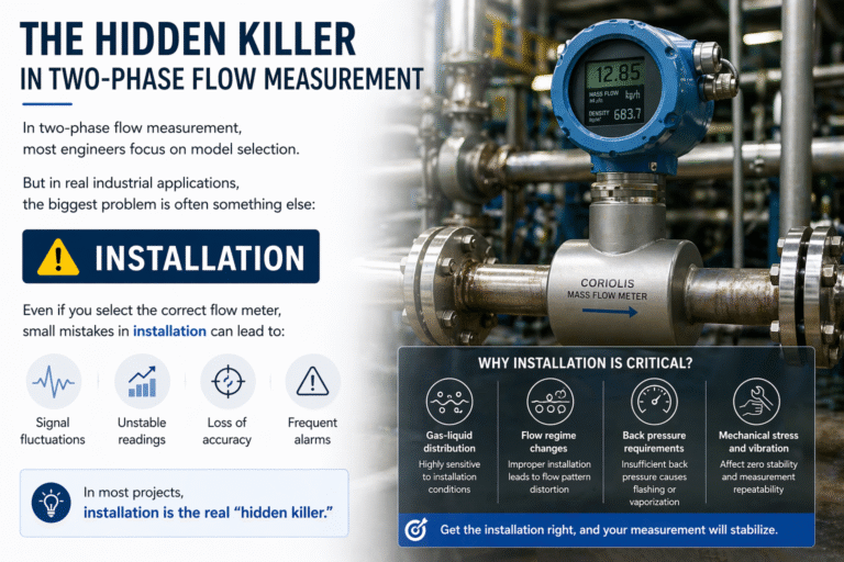
3.3 Coriolis mass flowmeters: gas bubbles and measurement-tube vibration
Coriolis mass flowmeters are widely used because they directly measure mass flow under suitable operating conditions.
Unlike volumetric flowmeters, their primary mass flow measurement does not require converting a volumetric flow rate using an assumed process density.
However, this does not mean that Coriolis meters are immune to entrained gas.
A Coriolis flowmeter uses vibrating measurement tubes to determine mass flow.
The meter also uses the vibration characteristics of the tubes to determine fluid density.
When gas bubbles enter the measuring tubes, several effects may occur.
Changes in vibration behavior
Entrained gas can change the effective dynamic behavior of the fluid inside the vibrating tubes.
Gas bubbles and liquid do not necessarily move in perfect synchronization during tube vibration, which can introduce additional measurement errors.
Increased vibration damping
Gas–liquid mixtures may increase vibration damping under certain conditions.
The meter’s drive system may need to supply more energy to maintain the required tube oscillation.
Some instruments provide drive-gain or similar diagnostic information that can help identify abnormal measurement conditions.
Unstable density measurements
The presence of gas changes the effective density and dynamic response of the fluid inside the measuring tubes.
Depending on the meter and process conditions, the reported density may become unstable or deviate from the expected single-phase liquid density.
Potential loss of measurement stability
At sufficiently high gas concentrations or under unstable flow regimes, the meter may experience substantial measurement errors or difficulty maintaining stable tube oscillation.
Some modern Coriolis flowmeters include advanced signal processing, diagnostic functions, or technologies intended to improve performance in the presence of entrained gas.
These capabilities can extend the useful operating range, but their performance limits vary considerably among manufacturers and models.
A meter advertised as capable of handling entrained gas should therefore be evaluated against the actual gas fraction, fluid properties, flow rate, and required accuracy.
Important: A Coriolis mass flowmeter designed for single-phase service should not automatically be treated as an accurate multiphase flowmeter simply because it measures mass directly.
4. Why Do Pressure Readings Fluctuate During Two-Phase Flow?
Flowmeters are not the only instruments affected by gas–liquid flow.
Pressure transmitters may also display abnormal or rapidly changing values.
However, it is important to distinguish between genuine process pressure fluctuations and measurement-system errors.
4.1 Genuine pressure fluctuations
When large gas pockets and liquid sections travel alternately through a pipeline, the local pressure may change dynamically.
Because gases are much more compressible than liquids, the response of the system can change as the gas content varies.
Intermittent flow can also interact with pumps, valves, and downstream restrictions, producing pressure oscillations.
In such cases, the pressure transmitter may be accurately measuring real process fluctuations.
Replacing or recalibrating the transmitter will not eliminate the underlying hydraulic instability.
4.2 Pressure measurement installation problems
A second possibility is that gas becomes trapped in pressure sensing connections originally intended for liquid service.
Depending on the installation arrangement, trapped gas can create hydrostatic errors, delayed response, or signal instability.
Pressure transmitters installed with impulse lines should therefore be checked for trapped gas, blocked connections, and improper routing.
Technicians should also consider mechanical vibration, electrical noise, and process-control oscillation as alternative causes of unstable pressure readings.
Not every fluctuating pressure signal is caused by two-phase flow.
5. Cavitation vs. Flashing: What Is the Difference?
Cavitation and flashing are often discussed together because both involve liquid vaporization caused by a reduction in pressure.
However, they describe different downstream conditions.
5.1 Cavitation: vapor bubbles form and collapse
Cavitation occurs when local liquid pressure falls below the saturation vapor pressure, causing vapor bubbles to form.
As the liquid moves into a region where pressure recovers above the vapor pressure, these bubbles may collapse rapidly.
Bubble collapse can generate localized pressure pulses and intense mechanical stresses.
Common symptoms include:
- Crackling or rattling noise.
- Increased vibration.
- Reduced pump or valve performance.
- Surface pitting and material erosion.
- Damage to pump impellers, valve trims, or other wetted components.
For example, cavitation may develop near a centrifugal pump impeller inlet if the available suction conditions are insufficient.
In pump applications, the available Net Positive Suction Head (NPSH) must be evaluated against the pump manufacturer’s requirements over the intended operating range.
Cavitation can also occur within control valves when local pressure falls below the liquid vapor pressure and subsequently recovers.
5.2 Flashing: vapor remains downstream
Flashing occurs when a liquid undergoes vaporization due to pressure reduction and the downstream pressure remains below its saturation vapor pressure.
Unlike cavitation, the vapor phase does not immediately collapse after passing through the restriction.
Instead, a gas–liquid mixture can continue flowing downstream.
Flashing may cause high mixture velocities, erosion, excessive noise, and difficulties in downstream flow measurement.
It is especially important in control valve sizing and downstream piping design.
5.3 Cavitation and flashing compared
| Characteristic | Cavitation | Flashing |
|---|---|---|
| Initial cause | Local pressure falls below vapor pressure | Pressure reduction causes vaporization |
| Downstream pressure | Recovers sufficiently to collapse vapor bubbles | Remains below vapor pressure |
| Vapor behavior | Bubbles form and collapse | Vapor persists downstream |
| Typical damage | Localized pitting and erosion from bubble collapse | Erosion associated with high-velocity two-phase flow |
| Common locations | Pumps and control valves | Control valves and downstream piping |
One important point is that not all gas–liquid two-phase flow is cavitation.
Air entrainment and dissolved-gas release may produce two-phase flow without the same vapor-bubble collapse mechanism.
This distinction helps prevent incorrect troubleshooting decisions.
6. Practical Troubleshooting Guide for Unstable Flow and Pressure Readings
When flow and pressure readings fluctuate, it is tempting to adjust transmitter damping, recalibrate the instrument, or replace the sensor.
However, such actions may only conceal the symptoms.
A systematic investigation should begin with the process conditions.
Step 1: Confirm the instrument is functioning correctly
Before assuming a process problem, verify the basic condition of the measurement system.
Check the power supply, wiring, grounding, transmitter diagnostics, sensor configuration, and communication signals.
For a flowmeter, confirm that the configured units, measuring range, and output settings match the intended application.
For a differential pressure transmitter, check whether impulse-line problems or incorrect zero settings may be affecting the measurement.
Step 2: Compare process trends
Examine trends from the flowmeter, pressure transmitter, tank level transmitter, pump, and control valve.
Look for relationships such as:
- Flow fluctuations beginning when tank level falls.
- Pressure fluctuations appearing after valve movement.
- Increased flow noise at higher operating rates.
- Coriolis density fluctuations occurring alongside unstable mass flow readings.
- Repeated measurement disturbances during startup or shutdown.
These correlations may help identify the operating conditions responsible for the problem.
Step 3: Inspect the pump suction system
Check whether the pump has sufficient liquid supply and whether the suction piping is properly sealed.
Look for low tank levels, vortex formation, restricted suction lines, and operating conditions associated with inadequate NPSH.
If the pump produces abnormal noise or vibration, investigate cavitation and air entrainment.
Step 4: Identify potential gas accumulation points
Review the pipeline layout.
Local high points, horizontal sections, and poorly designed pipe routing may allow gas to accumulate.
Where appropriate, investigate whether correctly designed venting arrangements or modifications to the pipe configuration are necessary.
Do not open or vent a pressurized system without following approved site safety procedures.
Step 5: Examine pressure reduction points
Inspect control valves, restrictions, filters, or other components where substantial pressure losses may occur.
Compare operating pressure and temperature with the liquid’s vapor pressure.
This helps determine whether vapor formation is physically possible under the existing conditions.
Step 6: Evaluate the flowmeter technology and installation
Confirm whether the flowmeter is suitable for the actual process conditions.
A meter selected for single-phase liquid measurement may not meet its stated accuracy when significant entrained gas is present.
Review the manufacturer’s installation instructions and performance limitations before changing the meter configuration.
Common symptoms and possible causes
| Observed symptom | Possible cause | Recommended investigation |
|---|---|---|
| Flow becomes unstable as tank level decreases | Air entrainment at pump suction | Check suction submergence, vortex formation, and leaks |
| Electromagnetic flowmeter gives erratic readings | Entrained gas or incomplete pipe filling | Check pipe filling, gas accumulation, and diagnostics |
| Differential pressure flow fluctuates | Two-phase flow or trapped gas in impulse lines | Inspect process conditions and impulse lines |
| Coriolis density fluctuates unexpectedly | Entrained gas or changing fluid properties | Review density trends and instrument diagnostics |
| Control valve produces unusual noise | Cavitation, flashing, or other hydraulic effects | Check pressure drop, vapor pressure, and valve operating conditions |
| Pump vibration increases | Cavitation, air entrainment, or mechanical problems | Check suction conditions and pump health |
| Pressure transmitter oscillates | Actual pressure pulsation or sensing-system issue | Compare process trends and inspect transmitter connections |
These symptoms are diagnostic clues, not definitive proof of two-phase flow. Multiple mechanisms can produce similar behavior.
7. How to Reduce Two-Phase Flow Measurement Problems

Preventing gas-related measurement errors generally requires improving the process conditions rather than relying exclusively on transmitter configuration.
Maintain adequate pump suction conditions
Ensure that the pump operates with sufficient liquid supply and within the manufacturer’s recommended suction conditions.
Avoid excessive tank drawdown and suction arrangements that encourage vortex formation.
Inspect suction-side connections for possible air ingress.
Minimize unnecessary pressure reductions
Review significant restrictions and valve pressure drops.
Where vaporization is a concern, assess the process pressure and temperature conditions and consider suitable equipment design modifications.
Control valve cavitation and flashing should be addressed through proper valve selection and hydraulic design rather than merely increasing instrument signal damping.
Avoid gas accumulation near flowmeters
Where practical, design pipeline routing to minimize trapped gas near the measuring section.
For electromagnetic flowmeters, maintain a completely filled measuring tube.
For other flowmeter technologies, follow the manufacturer’s installation recommendations concerning orientation, straight pipe requirements, and allowable process conditions.
Use appropriate gas removal equipment
In suitable applications, air separators, degassing equipment, or properly designed venting systems may reduce entrained or accumulated gas.
However, these devices must be selected according to the fluid, pressure, temperature, and process safety requirements.
They are not universally appropriate for every industrial liquid.
Select measurement technology based on actual operating conditions
The expected presence of gas should be considered during flowmeter selection.
Questions to ask include:
- Is the process liquid normally free of gas?
- Can air enter during low-level operation or startup?
- Does the liquid contain dissolved gas that may be released?
- Is vaporization possible across control valves or restrictions?
- What accuracy is required during gas-containing conditions?
- Is the objective to measure the liquid phase alone or the combined mixture?
For applications with unavoidable and significant two-phase flow, a dedicated multiphase measurement solution or additional phase separation may be necessary.
A conventional single-phase flowmeter cannot always meet the required accuracy simply through software adjustments.
8. Conclusion
Unstable flow and pressure readings do not always indicate a defective instrument.
Air entering through a pump suction connection, gas released from solution, vapor formation across a control valve, or gas accumulation inside a pipeline can all change the characteristics of the flowing medium.
Once a single-phase liquid becomes a gas–liquid mixture, its behavior may become much more complex.
Bubbly flow, slug flow, stratified flow, and other flow regimes can influence pressure, velocity, density, and instrument performance.
Electromagnetic, differential pressure, and Coriolis flowmeters respond differently to these conditions, but none should automatically be assumed to provide accurate liquid-only measurements under arbitrary two-phase flow conditions.
The most effective troubleshooting approach is to examine the complete process rather than focusing on the flowmeter alone.
Check the tank level, pump suction conditions, pressure trends, valve operation, pipeline layout, and instrument diagnostics.
Sometimes the flowmeter is accurately reporting an unstable process. Sometimes the flow conditions are causing measurement error. Understanding the difference is the key to solving the problem.
Published by Zero Instrument — Just Measure It
Zero Instrument provides industrial flow measurement solutions, including electromagnetic flowmeters, Coriolis mass flowmeters, ultrasonic flowmeters, and differential pressure measurement instruments for industrial applications.
Suggested SEO Meta Description: Learn why flow and pressure readings fluctuate due to gas–liquid two-phase flow, entrained air, cavitation, and flashing, and how to troubleshoot flowmeters.