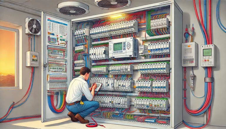
In industrial automation, PLCs (Programmable Logic Controllers) often work with sensors, switches, and other input-output devices to control and monitor processes. When wiring these devices to PLC inputs and outputs, two common configurations are used: PNP (Positive-Negative-Positive) and NPN (Negative-Positive-Negative). These configurations are distinguished by the direction of current flow and the electrical polarity required for the devices to operate. Choosing the correct configuration is crucial for system compatibility and operational reliability.

1. Basics of Current Flow in PNP and NPN Configurations
The main difference between PNP and NPN wiring configurations lies in the direction of current flow:
- NPN Configuration (Negative-Positive-Negative): Also known as “Sinking” configuration, the current flows from the PLC input through the sensor and to ground (negative).
- PNP Configuration (Positive-Negative-Positive): Also known as “Sourcing” configuration, the current flows from the sensor through the PLC input and to the positive voltage source.
This distinction affects how sensors and switches are connected to the PLC’s inputs or outputs and how the PLC detects a signal.

2. NPN Configuration (Sinking)
In the NPN configuration:
- Wiring: The PLC’s input receives the current flow and is connected to the ground (negative terminal) when the sensor is activated.
- Current Direction: When a device, such as a sensor or switch, is triggered, current flows from the sensor’s output into the PLC input and then to the ground (GND or 0V).
- Signal Detection: When the sensor is triggered, the PLC detects a low (0V) signal on its input.
- Applications: The NPN configuration is commonly used in regions such as Asia and Japan, where it is traditionally the preferred wiring standard. This configuration is often chosen for its robustness against electrical noise, making it more suitable for environments with high electromagnetic interference (EMI).
Example Application: In an NPN sensor connected to a PLC input, when the sensor is triggered, it completes a path to ground, allowing current to flow from the sensor’s output to the ground. The PLC recognizes this low signal as an input.

3. PNP Configuration (Sourcing)
In the PNP configuration:
- Wiring: The PLC’s input receives the current from the sensor when the sensor is activated and is connected to the positive voltage terminal.
- Current Direction: When a PNP device, such as a sensor, is triggered, current flows from the positive voltage source through the sensor and into the PLC input.
- Signal Detection: When the sensor is triggered, the PLC detects a high voltage signal, typically the same as the positive supply voltage.
- Applications: PNP configuration is widely used in European systems and is considered more intuitive for users unfamiliar with PLC wiring. Many find PNP wiring simpler and more straightforward since it follows the idea that “current flows into the device” to signal activation.
Example Application: In a PNP sensor, when the sensor is triggered, it provides a path from the positive voltage to the PLC input. The PLC detects this high voltage as a signal input, registering the sensor’s activation.
4. Key Differences Between PNP and NPN
| Aspect | PNP (Sourcing) | NPN (Sinking) |
|---|---|---|
| Current Flow | Positive to negative | Negative to ground |
| Signal when Triggered | High (positive voltage) | Low (ground, 0V) |
| Preferred Regions | Europe | Asia, Japan |
| Wiring Simplicity | More intuitive for some | Better in high-EMI environments |
| Common Naming | “Sourcing” configuration | “Sinking” configuration |
5. Considerations When Choosing Between PNP and NPN
Selecting the correct configuration requires considering several factors:
- System Compatibility: Always ensure that the PLC and sensors are compatible with the chosen wiring configuration. Some PLCs are designed for specific configurations, while others may support both.
- Regional Standards: Certain regions have standards that favor one configuration over the other. In Europe, PNP is more commonly used, while in Asia, NPN is standard.
- Environmental Conditions: If the environment has high levels of electrical noise (e.g., in industrial settings with motors, welding equipment, or high-voltage systems), NPN wiring may be more resistant to interference due to its grounding connection.
- Ease of Troubleshooting: Some users find PNP configurations more straightforward since they are more intuitive to visualize. PNP often aligns with the idea of providing a positive voltage to indicate a signal.

6. Practical Examples in PLC Wiring
To better illustrate the application of these configurations, let’s look at two examples of wiring a sensor to a PLC in both configurations:
PNP Example: Connect the negative terminal (GND) to the sensor’s common, then wire the sensor’s output directly to the PLC input. When the sensor activates, it connects the positive voltage to the PLC input, signaling a high input.
NPN Example: Connect the positive voltage to the sensor’s common, and wire the sensor’s output to the PLC input. When the sensor activates, it connects the PLC input to ground, signaling a low input.

Conclusion
Understanding the differences between PNP and NPN configurations in PLCs is essential for proper wiring, system compatibility, and reliable operation in industrial automation. The choice between these configurations will depend on the specific requirements of the application, regional standards, and environmental factors. Always consult the PLC and sensor documentation to verify compatibility with the chosen wiring method and ensure optimal performance in the field.
