A stable flow field is the premise of the accurate measurement of the thermal instrument. Therefore, please note the following points when installing the instrument.
Installation direction
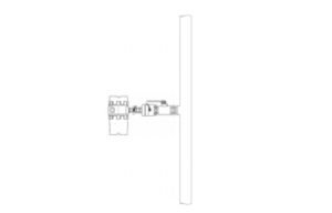
- Horizontal installation
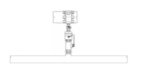
- Vertical installation
The process pressure must not exceed 2MPa when installing.
Pipe requirements
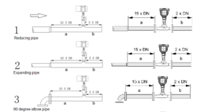
If the Interference sources (i.e. bends, reduce, valves, T tubes, etc.) exist on the instrument intake
pipe, measures must be taken to minimize their impacts on measurement performance
The following diagrams describe the recommended minimum straightway lengths of some types of pipe.
The straightway length should be as long as possible while the room is sufficient. Without the consideration of other factors, the recommended minimum straightway lengths are:
front straightway length: 20×DN
rare straightway length: 5×DN
The recommended straightway lengths are minimum, increased straightway lengths improve the instrument performance.
If multiple Interference sources exist in front of the instrument, the recommended straightway lengths are absolute.
The control valves are recommended to be placed at a rare instrument.
For the light gases, such as helium and hydrogen, front straightway lengths should be doubled.
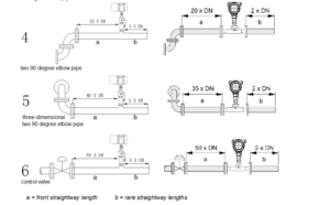
Control valves and shut-off valves should be placed at a rare instrument.
Installation Steps
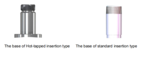
The base of the thermal flowmeter
No welding in an explosive environment
Carry out the welding operation in accordance with the requirements of the special environment.
When installing, place the base on the top of the pipe, and make the through-hole of the base be perpendicular to the axis of the pipe. The good welding location of base and welding process is as below.
The installation of standard insertion type
Identify an appropriate location for the flow meter.
Confirm the inner diameter and wall thickness of the pipe
Place the other part of the meter into the ball valve, and calculate the insertion depth according to the inner diameter and wall thickness of the pipe. This step doesn’t need to screw the nut by hand.
Turn the connecting rod of the sensor to make the mark direction of the sensor the same flow direction.
According to the calculated data on-site, ensure the insertion depth by the corresponding calibration on the connecting rod, and then screw the nut tightly.
If the meter is horizontal installation, the display of the meter can be installed in the direction of 90°,180°, or 270° to meet various requirements.
The installation of hot-tapped insertion type
Before installation, please confirm the connection type and install fittings.
Before installation, the site must be shut down, and strictly follow the rules of the factory.
Identify an appropriate location for the flow meter.
According to the length requirement of the meter, cut the pipe, and install the flanges and bolts on the pipe.
Ensure the mark direction of the meter is as the same flow direction, the display is perpendicular to the horizontal plane, the axis of the pipeline is paralleled to the horizontal plane, the error can’t be more than ±2.5, and then fix the meter by bolts.