1. Site Assessment
1.1 Pipe Conditions
Ensure the inner wall of the pipeline is smooth, corrosion-free, and free of deposits.
Installation should be on horizontal or vertical straight sections of pipe.
Avoid installing near elbows, branch connections, or diameter reductions.
1.2 Fluid Characteristics
The fluid must have a minimum conductivity (typically > 5 μS/cm).
Avoid fluids containing excessive bubbles, solid particles, or fibrous matter.
1.3 Environmental Conditions
Ambient temperature should range between 5°C and 55°C.
The area must be free from strong electromagnetic interference, corrosive gases, and excessive vibration.
2. Selecting the Installation Method
In-line (Full Bore) Installation: Common for small to medium diameter pipes.
Side Mount Installation: For applications with limited space.
Inclined Installation: Used in special industrial situations for optimized flow measurement.
3. Tools and Materials Checklist
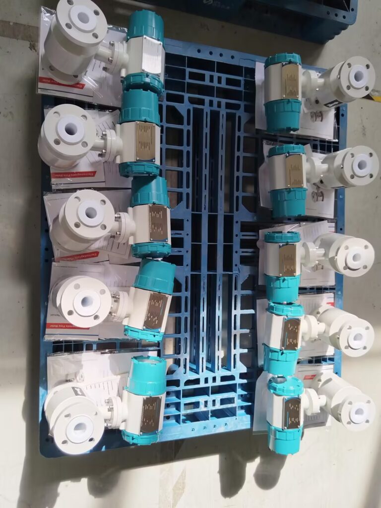
Flanges, bolts, gaskets for mechanical connection.
Electrical cables, power wires, and connectors.
Grounding ring or grounding electrode and related accessories.
4. Installation Procedure
4.1 Determine Installation Location
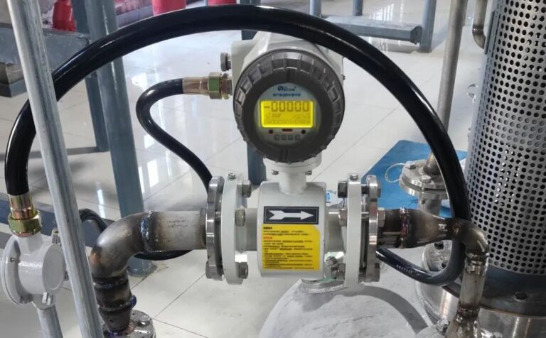
Align the flow direction arrow on the sensor with actual flow.
Prefer locations that are:
Always fully filled with fluid,
Easy to access for maintenance,
Free from large electrical equipment or strong magnetic fields.
4.2 Install Flanges
Flanges must match the sensor’s mating dimensions.
Tighten bolts evenly to avoid stress on the flowmeter body.
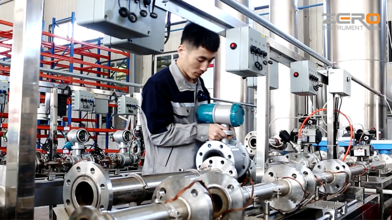
4.3 Mount the Flowmeter
Ensure alignment with the pipe axis—either horizontal or vertical.
Avoid mechanical shock and vibration during installation.
4.4 Electrical Connection
Follow wiring diagram provided by the manufacturer.
Use shielded cables rated for the site’s protection class.
Prevent cable stretching or pinching during routing.
4.5 Grounding
Ground the metal enclosure and grounding ring securely.
Resistance of grounding should be less than 10 ohms.
Avoid sharing the ground with other equipment.
5. Commissioning and Calibration
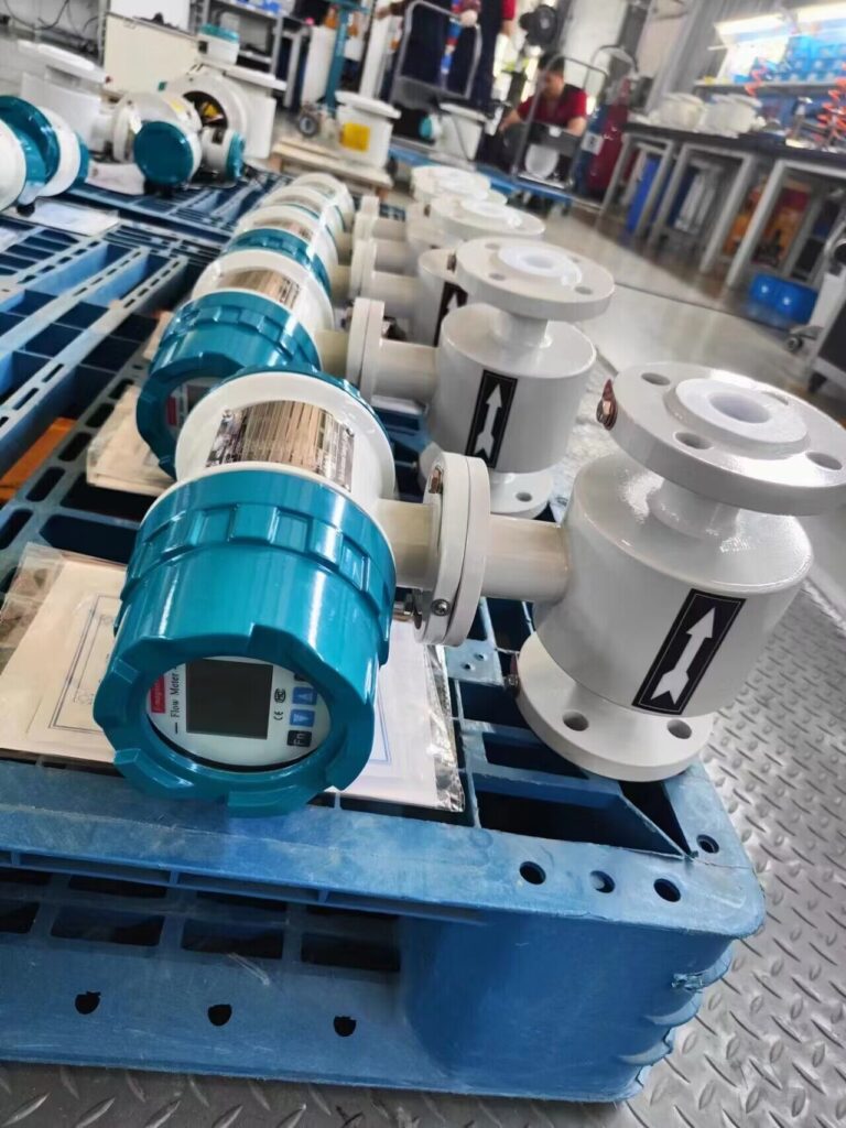
5.1 Power-On Check
Confirm all electrical connections are correct.
Check power supply voltage matches specifications.
Observe display and system self-check for errors.
5.2 Zero Calibration
Perform zero-point calibration when the fluid is at a standstill.
The flowmeter should output zero flow in this condition.
5.3 Full-Scale Calibration
At full flow rate, verify the output matches actual volume.
Adjust internal parameters to align with reference values.
5.4 Repeatability Testing
Conduct multiple tests under identical flow to check for repeatability.
Repeatability error should be within the manufacturer’s tolerance.
6. Key Installation Guidelines
6.1 Avoiding Measurement Errors
Do not install at pipe high points where air may accumulate.
Install air release valves where necessary.
Always ensure the sensor is completely filled with fluid during operation.
6.2 Straight Pipe Requirements
Upstream straight length ≥ 5D to 10D (D = pipe inner diameter).
Downstream straight length ≥ 5D.
Use reducers/expanders with ≤ 15° cone angle for pipe transitions.
6.3 Orientation Notes
Horizontal installation: Keep electrodes aligned horizontally.
Vertical installation: Recommended for fluids with solids to ensure uniform wear.
Flow should always be upward for vertical installations to maintain full pipe.
6.4 Vibration and Electromagnetic Considerations
Avoid installing on vibrating or unsupported pipe sections.
Stay away from strong magnetic sources like transformers or motors.
7. Special Situations and Illustrations
7.1 Long Pipeline or Drop Sections
Install an air vent valve at the highest point if the drop exceeds 5 meters.
Install a control valve downstream, not upstream, to avoid negative pressure.
7.2 Mixed or Corrosive Media
For abrasive or scaling fluids:
Use higher flow speeds (>2 m/s) to reduce fouling.
Consider narrower or lined sections to improve velocity.
For highly corrosive fluids, use grounding electrodes instead of grounding rings.
7.3 Insulated or Non-Metallic Pipes
Install metal grounding flanges or short metal pipe sections.
If unavailable, insert dedicated grounding electrodes into the pipeline.
8. Cable Laying & Electrical Wiring
Follow local regulations for open or concealed wiring.
Use separate cable trays or conduits to avoid signal interference.
Refer to the manufacturer’s signal and excitation wiring diagram.
Conclusion
Proper installation of an electromagnetic flowmeter ensures long-term accuracy, system reliability, and operational safety. Adhering to these procedures—site assessment, mounting practices, electrical configuration, and calibration—can significantly enhance performance in diverse industrial applications.
