Standard Installation Guide for Combustible and Toxic Gas Detectors - Just Measure it

Standard Installation Guide for Combustible and Toxic Gas Detectors

1. Overview

In industrial environments, proper installation of combustible and toxic gas detectors is essential for early leak detection, personnel safety, and fire/explosion prevention. This guide provides standard recommendations for installation height, spacing, positioning, and alarm thresholds.

2. Detector Placement Principles

The layout of detectors should be based on gas dispersion patterns after a leak. Detectors must be positioned so that in the event of a leak, gas concentrations can be detected before they reach hazardous levels.

Detectors should be installed near the following typical gas emission sources:

  • Dynamic seals on gas compressors and liquid pumps

  • Liquid and gas sampling ports

  • Drainage points and vent valves

  • Frequently disassembled flanges or frequently operated valve sets

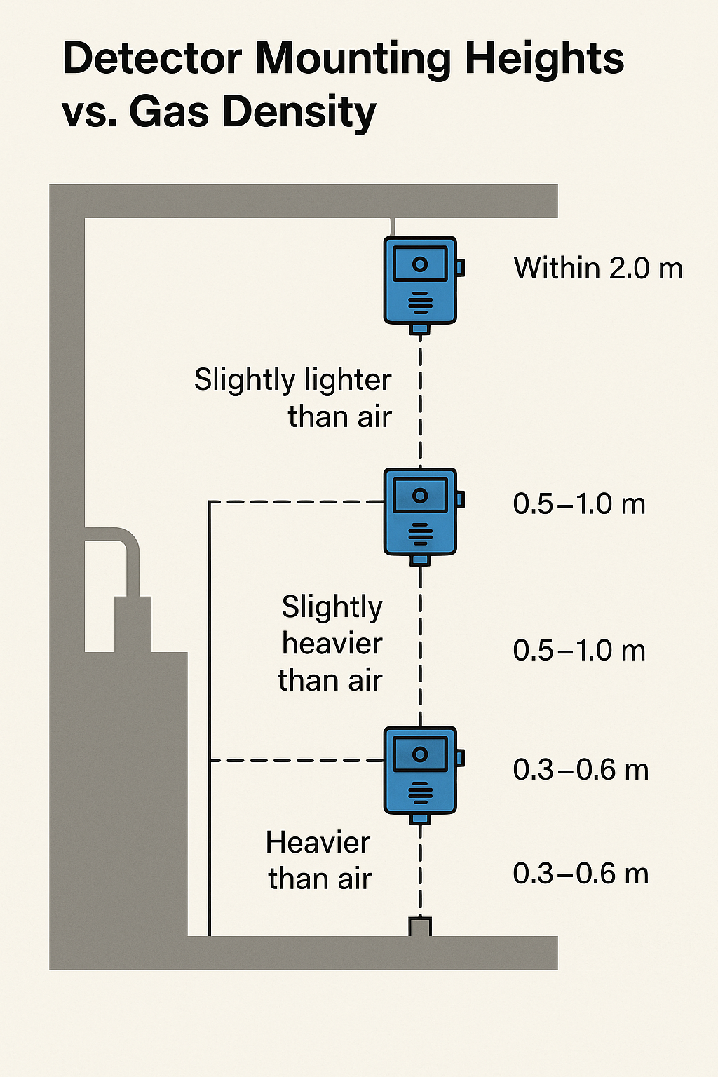
3. Gas Density and Mounting Height

Gas density relative to air determines the appropriate installation height:

Relative Molecular WeightClassificationRecommended Mounting Height
≥ 1.2Heavier than air0.3–0.6 m from the floor
1.0 – 1.2Slightly heavier0.5–1.0 m below the leak source
0.8 – 1.0Slightly lighter0.5–1.0 m above the leak source
≤ 0.8Lighter than airWithin 2.0 m above the leak source or at ceiling level

Diagram available: Mounting Height vs. Gas Density

4. Spacing Requirements

➤ Outdoor or Open Structures:

  • Combustible gas detectors: max 10 m from each leak source

  • Toxic gas detectors: max 4 m from each leak source

➤ Enclosed or Poorly Ventilated Areas:

  • Combustible gas detectors: max 5 m

  • Toxic gas detectors: max 2 m

5. Alarm Thresholds

Gas TypeLevel 1 AlarmLevel 2 Alarm
Combustible Gas≤ 25% LEL≤ 50% LEL
Toxic Gas≤ 100% OEL≤ 200% OEL
Oxygen (Overlimit)> 23.5% Vol
Oxygen (Deficiency)< 19.5% Vol

LEL: Lower Explosive Limit
OEL: Occupational Exposure Limit

6. Signal Handling and Alarm Display

  • Alarm signals should be sent to manned local control rooms, central control rooms, and fire control stations.

  • Visual and audible alarms must be installed at operator stations and field areas.

  • Field alarms should consider site layout, area size, equipment density, and airflow characteristics.

7. Detector Selection Guidelines

ApplicationRecommended Detector Type
Light hydrocarbons (e.g., methane)Catalytic combustion or infrared
Heavy hydrocarbons (e.g., hexane)Photoionization (PID)
HydrogenCatalytic, electrochemical, or thermal conductivity
Organic toxic gasesSemiconductor or PID
Inorganic toxic gasesElectrochemical
OxygenElectrochemical
Open areas with special conditionsLine-type gas detectors
Temperature-change-prone leaksInfrared imaging detectors
Pressure-leakage with sound impactAcoustic detectors
Temporary monitoringPortable gas detectors

8. Visual Aids (To Be Added)

  • Detector Mounting Height Chart

  • Detector Coverage Radius Illustration

  • Gas Density vs. Air Comparison Table

Share This Story, Choose Your Platform!

Contact Us

    Please prove you are human by selecting the key.
    Translate »