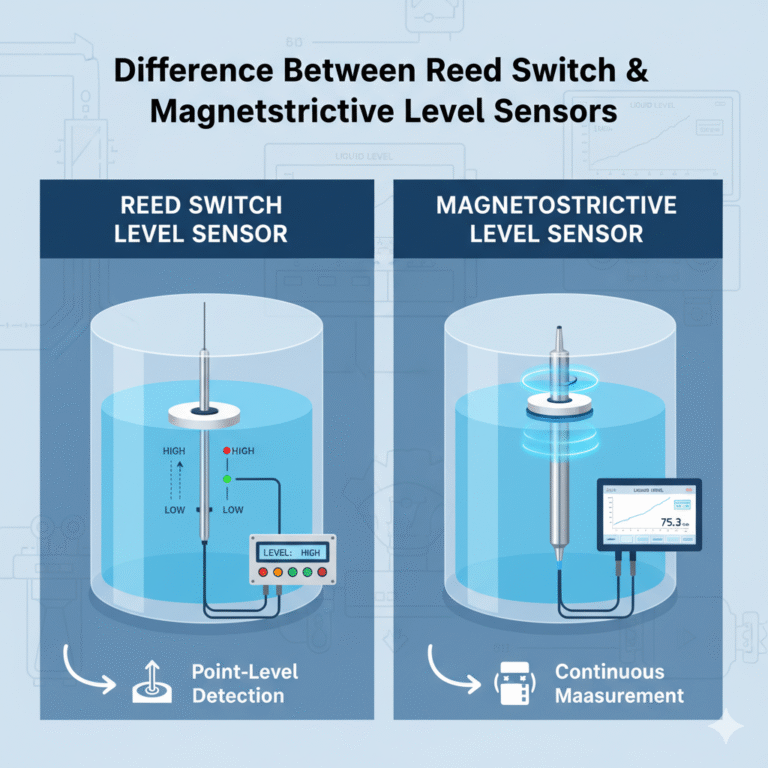
Magnetostrictive level transmitters use the magnetostrictive effect (where a magnetic field causes a metal rod to undergo elastic deformation and generate ultrasonic waves) to provide highly accurate level measurements. The key advantages are non-contact measurement, high precision (typically ±0.1%), and excellent stability. These devices are widely used for level monitoring in closed or open containers in industries such as petroleum, chemicals, and food processing.
1. Core Knowledge: Principles, Structure, and Key Parameters
1.1 Operating Principle (3-step core process)
Signal Trigger: The electronic head generates an electrical pulse, which travels along a built-in magnetostrictive waveguide wire, creating a circular magnetic field.
Magnetic Field Interaction: The float (containing a permanent magnet) inside the container creates an axial magnetic field. When this magnetic field intersects with the circular magnetic field, the waveguide wire undergoes mechanical deformation (strain pulse) due to the magnetostrictive effect.
Signal Calculation: The electronic head receives the strain pulse and calculates the float position by measuring the time difference between the electrical pulse emission and the strain pulse reception. This data, combined with the wave speed, is used to determine the actual liquid level.
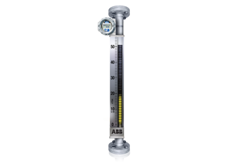
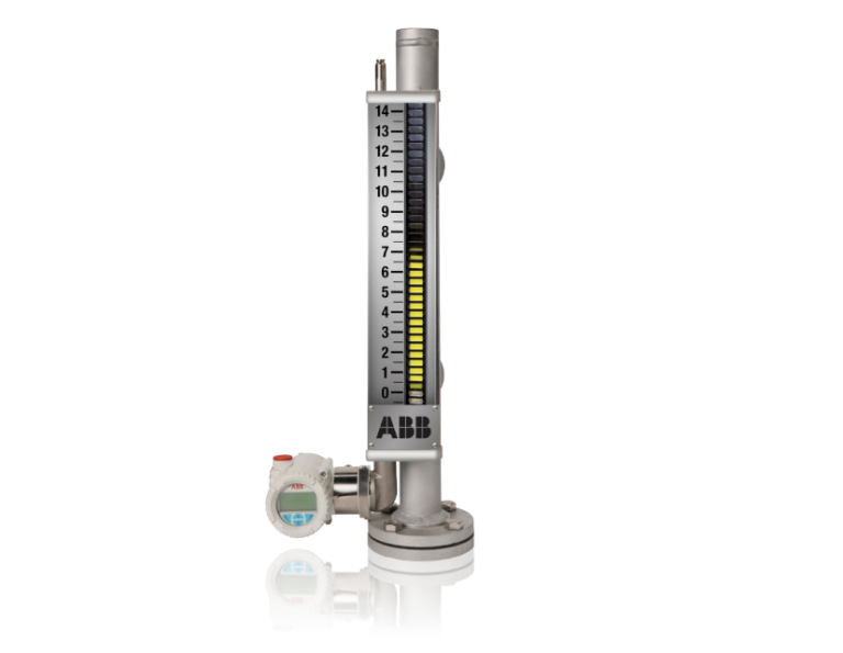
1.2 Core Components (4 main parts)
Electronic Head: The core control unit responsible for emitting electrical pulses, receiving strain pulses, and calculating the liquid level. It outputs either a 4-20mA analog signal or an RS485 digital signal.
Waveguide Wire: A carrier for the magnetostrictive effect, usually made of nickel-iron alloy. It must be kept straight and undamaged to ensure accurate measurements.
Float: Moves up and down with the liquid level. It contains a high-performance permanent magnet, and the strength of the magnetic field directly affects the interaction with the waveguide wire.
Measuring Tube: A protective stainless steel or plastic tube that shields the waveguide wire. The material must be compatible with the medium being measured (e.g., Hastelloy for strong acids, 316L stainless steel for the food industry).
1.3 Key Parameters (Selection and Usage)
Measurement Range: Typically 0.1m to 20m. Ensure the range is compatible with the actual height of the container to prevent accuracy degradation due to over-range or under-range conditions.
Medium Compatibility: The materials used for the float and measuring tube should be compatible with the medium to prevent corrosion or contamination.
Temperature/Pressure: Standard operating temperatures range from -40°C to 150°C, and pressure should be ≤10MPa. Specialized models are available for high-temperature or high-pressure conditions.
Accuracy: Industrial-grade accuracy is typically ±0.1% FS (Full Scale), while laboratory-grade models can achieve up to ±0.05% FS.
2. Common Faults and Troubleshooting (Organized by Fault Symptoms)
2.1 No Output Signal (Most Common Issue)
Possible Cause 1: Power Supply Failure
Troubleshooting Steps: Use a multimeter to check the supply voltage (typically 24V DC). Inspect the power cable for loose connections or short circuits.
Solution: Fix the power circuit to ensure stable voltage, secure loose connections, and replace damaged cables.
Possible Cause 2: Damaged Electronic Head
Troubleshooting Steps: After disconnecting the power, check the electronic head indicator light (it should be green when powered). Replace the electronic head with the same model for testing.
Solution: Replace the faulty electronic head. Ensure proper waterproof sealing if installed outdoors or in a humid environment.
Possible Cause 3: Broken Waveguide Wire
Troubleshooting Steps: Disconnect the float and manually pull on the waveguide wire. If it feels loose or has no resistance, it may be broken. Visually inspect the measuring tube.
Solution: Replace the waveguide wire. When installing, ensure it is straight and not twisted (as bending can cause signal disruption).
2.2 Incorrect Output Signal (Accuracy Issues)
Possible Cause 1: Float Sticking
Troubleshooting Steps: Check if the float moves with the liquid level. Manually move the float to feel for any resistance. Inspect the measuring tube for debris or scaling.
Solution: Use a compatible solvent to clean the measuring tube and remove debris or scaling. If the float is deformed, replace it with the same specification.
Possible Cause 2: Reduced Magnetic Strength of the Float
Troubleshooting Steps: Use a Gauss meter to measure the float’s surface magnetism. If it is below 80% of the standard value, replace the float. Check for prolonged exposure to high temperatures (which can accelerate magnetism loss).
Solution: Replace the float and avoid exposing it to temperatures above 150°C for extended periods.
Possible Cause 3: Calibration Parameters Lost
Troubleshooting Steps: Check the electronic head for “calibration error” messages. Compare the actual liquid level with the displayed value. If the deviation exceeds 1%, recalibrate.
Solution: Recalibrate according to the manual (using a standard liquid level gauge) and save the calibration parameters after completion.

2.3 Frequent Signal Fluctuations (Unstable Output)
Possible Cause 1: External Magnetic Interference
Troubleshooting Steps: Check if there are strong magnetic fields nearby (e.g., large motors, electromagnets). Observe whether the fluctuations correlate with the operation of external equipment.
Solution: Move the level transmitter away from strong magnetic field sources (minimum distance of 1m). Use shielded signal cables and ensure proper grounding.
Possible Cause 2: Severe Medium Fluctuations
Troubleshooting Steps: Check if the container experiences mixing, feeding impacts, or other disturbances that could cause the liquid level to fluctuate rapidly.
Solution: Install a baffle inside the container to reduce fluctuations. Adjust the electronic head’s “filtering parameters” to extend the signal sampling time.
Possible Cause 3: Loose or Oxidized Wiring
Troubleshooting Steps: Inspect the signal wiring terminals (4-20mA or RS485) for signs of oxidation or looseness. Use a multimeter to check for poor connections in the signal loop.
Solution: Clean the terminals with sandpaper, re-secure the wiring, and replace any old or worn signal cables.
2.4 Damaged Measurement Tube
Possible Cause: Corrosion from the medium, external impact, or prolonged exposure to high temperature/pressure can cause material aging.
Troubleshooting Steps: Visually inspect the measurement tube for cracks or holes. Check for signs of medium leakage.
Solution: Replace the measurement tube with one made from a material compatible with the medium. Avoid impacts during installation and regularly check for signs of aging.