
Selecting a level measurement instrument should always begin with the process conditions, not the instrument brand.
Before choosing a level transmitter or level switch, engineers need to understand several key factors:
- Process medium and its chemical properties
- Operating temperature and pressure
- Foam formation and surface turbulence
- Vapor and steam conditions inside the vessel
- Tendency of the medium to crystallize, solidify, or accumulate on surfaces
- Variations in liquid density
- Tank geometry and internal obstructions
- Required measurement accuracy and control functions
Once these conditions are understood, the appropriate measurement technology becomes much easier to determine.
Radar, ultrasonic, differential pressure, and float-type instruments can all be used for liquid level measurement. However, they work according to different physical principles and respond differently to actual process conditions.
Understanding the measurement principle and its limitations is often more important than simply comparing measuring ranges and accuracy specifications.
1. Radar Level Transmitters
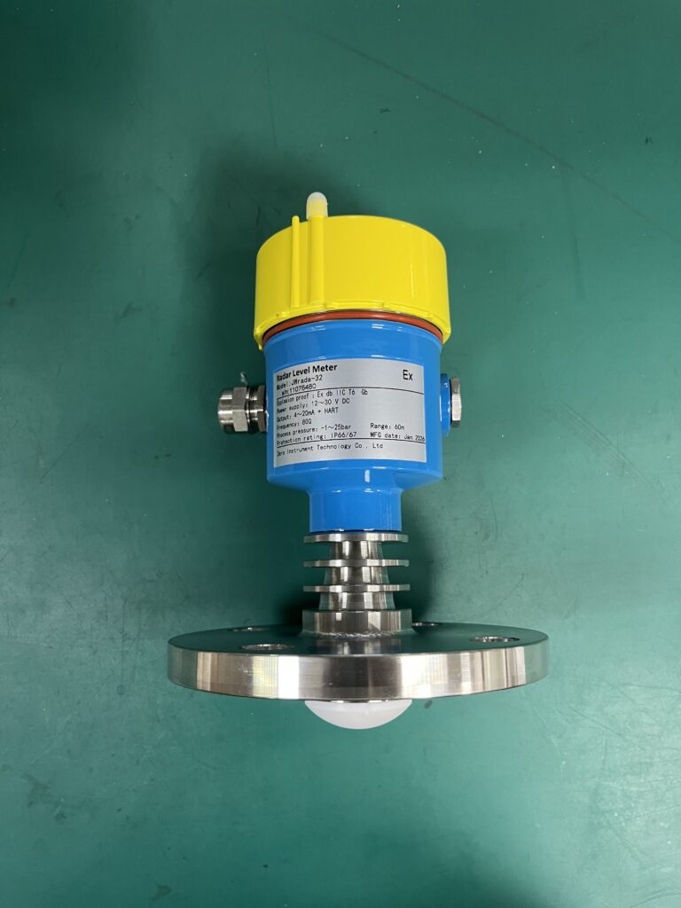
Measurement principle: Electromagnetic waves · Time of flight · Non-contact measurement
How It Works
A radar level transmitter emits electromagnetic waves toward the liquid surface through an antenna. When the waves encounter the liquid surface, part of the signal is reflected back to the instrument.
The transmitter calculates the distance between the antenna and the liquid surface based on the signal travel time. The liquid level is then calculated using the configured tank height and reference point.
Radar measurement does not rely on sound transmission through the gas space. Therefore, changes in gas temperature, pressure, and composition generally have less influence on the measurement than they do on ultrasonic instruments.
Radar level transmitters are widely used in storage tanks, chemical reactors, pressure vessels, and applications involving vapor or changing atmospheric conditions.
Factors Affecting Measurement Performance
1. Internal obstructions and false echoes
Agitator shafts, heating coils, reinforcing structures, and inlet pipes can reflect radar signals. These reflections may interfere with the actual liquid surface echo.
If the antenna is installed too close to the tank wall or directly above the filling inlet, the measured level may fluctuate.
During commissioning, engineers should examine the echo curve, identify fixed interference signals, and configure appropriate false-echo suppression where supported by the instrument.
2. Antenna installation conditions
The installation nozzle must be checked carefully.
An excessively long nozzle, insufficient nozzle diameter, or unsuitable antenna position can weaken or distort the reflected signal.
For small tanks or vessels with many internal structures, installation position is often more important than parameter adjustment.
3. Dielectric constant and foam
The dielectric properties of the liquid affect the strength of the reflected radar signal. Liquids with very low dielectric constants may produce relatively weak echoes, requiring careful instrument selection.
Thick foam can also affect the reflected signal. The actual impact depends on foam properties, radar frequency, antenna design, and the dielectric characteristics of the liquid underneath.
4. Antenna contamination
Although radar transmitters are non-contact instruments, the antenna itself may accumulate deposits.
Sticky materials, crystallization, or condensation on the antenna can affect signal transmission and reception. In applications with heavy buildup, antenna design and maintenance accessibility should be considered.
Typical Applications and Limitations
Radar level transmitters are particularly suitable for continuous level measurement in storage tanks and process vessels where temperature, pressure, or gas-phase conditions vary.
However, radar is not completely immune to interference. Proper antenna selection, installation, echo evaluation, and process compatibility remain essential.
2. Ultrasonic Level Transmitters
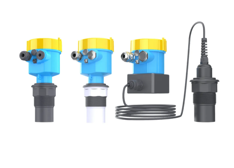
Measurement principle: Sound waves · Time of flight · Non-contact measurement
How It Works
An ultrasonic level transmitter emits high-frequency sound waves toward the liquid surface.
When the sound waves reach the liquid surface, they are reflected back to the sensor. The instrument calculates the distance between the sensor and the liquid surface based on the round-trip travel time.
The liquid level is then calculated from the configured measuring range.
Ultrasonic instruments do not need to contact the liquid, making them convenient for applications where simple installation and non-contact measurement are preferred.
They are commonly used in water tanks, wastewater treatment plants, open channels, and other atmospheric liquid storage applications.
Factors Affecting Measurement Performance
1. Temperature variations in the gas space
Unlike radar, ultrasonic measurement depends on sound propagation through the gas above the liquid.
The speed of sound changes with gas temperature. Significant temperature variations or temperature gradients can therefore introduce measurement errors.
Many ultrasonic transmitters include temperature compensation, but compensation may not completely eliminate errors caused by complex temperature gradients.
2. Steam and vapor
Heavy steam or vapor conditions can interfere with ultrasonic signal transmission and reception.
For this reason, ultrasonic instruments are generally less suitable for vessels containing significant steam or unstable gas-phase conditions.
3. Foam and surface conditions
Thick foam can absorb or scatter ultrasonic energy, preventing a stable echo from returning to the sensor.
Strong surface turbulence, splashing, and rapidly changing liquid surfaces may also cause unstable readings.
4. Vacuum conditions
Conventional ultrasonic level measurement is not suitable for vacuum environments because sound requires a medium through which to propagate.
5. Installation interference
The sensor should be installed away from internal beams, pipes, tank walls, and filling streams.
If the measured level fluctuates unexpectedly, the cause may be an obstruction or an unsuitable mounting position rather than a defective instrument.
Typical Applications and Limitations
Ultrasonic level transmitters are suitable for water and wastewater applications under relatively stable atmospheric conditions.
They are especially practical when the gas space is relatively clean, the liquid surface is not excessively turbulent, and foam formation is limited.
For vessels with significant steam, large temperature gradients, heavy foam, or vacuum conditions, other measurement technologies should be evaluated.
3. Differential Pressure Level Measurement
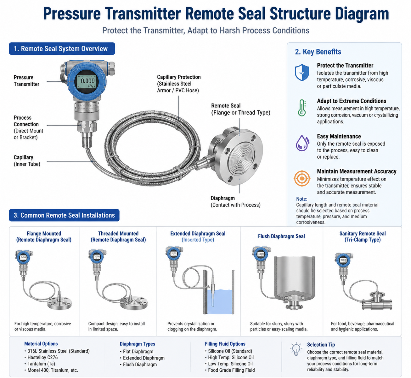
Measurement principle: Hydrostatic pressure · ΔP = ρgh · Density dependent
How It Works
A differential pressure transmitter does not directly detect the liquid surface. Instead, it measures the pressure generated by the liquid column and converts that pressure into a level value.
As the liquid level increases, the hydrostatic pressure increases. When the liquid level decreases, the pressure decreases accordingly.
The basic relationship is:
ΔP = ρ × g × h
Where:
- ΔP = Hydrostatic pressure or differential pressure
- ρ = Liquid density
- g = Gravitational acceleration
- h = Liquid height
For an open tank, the hydrostatic pressure at the bottom is directly related to the liquid height and density.
For a closed vessel, the gas-space pressure must also be considered. A typical differential pressure arrangement connects the high-pressure side to the liquid side and the low-pressure side to the vapor space. This allows the transmitter to compensate for the vessel’s gas pressure and measure the pressure difference associated with the liquid column.
Differential pressure level measurement is widely used in chemical plants, refineries, power stations, and industrial process vessels.
Common installation arrangements include impulse piping, remote diaphragm seals, and wet-leg systems.
Factors Affecting Measurement Performance
1. Liquid density variations
Density is one of the most important factors affecting differential pressure level measurement.
Even when the actual liquid level remains unchanged, a change in liquid temperature may cause the liquid density to change.
Because the transmitter measures pressure rather than directly detecting the liquid surface, it cannot independently distinguish whether a pressure change is caused by a level change or a density change.
Therefore, significant density variations can introduce level measurement errors.
2. Impulse line problems
Common impulse piping problems include:
- High-pressure-side blockage
- Liquid accumulation in the low-pressure impulse line
- Gas trapped inside impulse piping
- Freezing during cold weather
- Leakage through manifold valves
- Incorrect installation or elevation differences
When the DCS level indication drifts while the actual liquid level remains stable, the impulse piping and valve manifold should be checked before replacing the transmitter.
3. Remote diaphragm seal systems
Remote diaphragm seals can reduce problems associated with impulse line blockage, freezing, and direct process contact.
However, capillary filling fluid, ambient temperature variations, capillary routing, and elevation differences can introduce additional measurement errors.
The installation arrangement must therefore be considered during instrument selection and engineering design.
4. Static pressure head and installation
For closed vessels and wet-leg applications, the pressure head created by the installation arrangement must be properly accounted for.
Incorrect transmitter elevation, unsuitable impulse line routing, or an incorrectly configured zero point can result in significant measurement deviations.
Typical Applications and Limitations
Differential pressure level measurement is suitable for vessels where process pressure conditions are known and liquid density remains sufficiently stable or can be compensated for.
It is particularly useful in established industrial processes, including boilers, chemical reactors, and pressurized storage vessels.
However, density variations and impulse piping conditions must be carefully evaluated before selecting this technology.
4. Float-Type Level Instruments
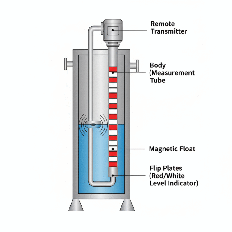
Measurement principle: Buoyancy · Magnetic coupling · Reed switches or mechanical movement
How It Works
Float-type level instruments operate according to the principle of buoyancy.
As the liquid level rises, the float moves upward. When the liquid level falls, the float moves downward.
The movement can be transferred through magnetic coupling, reed switches, or mechanical structures to generate a level indication or electrical signal.
Different float-type instruments serve different purposes:
- Magnetic level indicators provide local continuous level indication.
- Magnetic float transmitters can provide continuous electrical level signals.
- Float level switches provide discrete high-level or low-level switching signals.
These instruments are commonly used in water tanks, oil tanks, small storage vessels, sumps, and applications requiring simple level alarms or pump control.
Factors Affecting Measurement Performance
1. Liquid viscosity
Highly viscous liquids may restrict float movement, causing delayed response or mechanical sticking.
2. Crystallization and material buildup
If the liquid tends to crystallize, solidify, or accumulate on surfaces, deposits may prevent the float from moving freely.
The float chamber and mechanical components should be checked for compatibility with the process medium.
3. Foreign materials and suspended solids
Wastewater containing fibers, plastic materials, or other debris may become entangled around the float or its moving components.
This can prevent normal operation and lead to incorrect switching or indication.
4. Liquid density variations
Float immersion depth depends on the balance between buoyancy and the weight of the float.
When liquid density changes significantly, the float’s immersion depth may also change, potentially affecting the switching point or measurement calibration.
Typical Applications and Limitations
Float-type instruments are suitable for relatively clean liquids where sufficient mechanical movement space is available and the measurement or control requirements are straightforward.
They are particularly practical for high-level alarms, low-level alarms, and pump start/stop control.
For highly viscous, crystallizing, or debris-containing liquids, the mechanical design and maintenance requirements should be evaluated carefully.
5. How to Choose the Right Level Measurement Technology
Understanding the operating principle is only the first step. The next step is matching the measurement technology to the actual process conditions.
The following table provides a preliminary selection reference.
| Process condition | Technologies to consider |
|---|---|
| Atmospheric water tanks | Ultrasonic or radar |
| High-temperature, high-pressure vessels | Radar or differential pressure |
| Closed vessels with significant vapor or steam | Radar or differential pressure |
| Boiler drum level measurement | Differential pressure or specialized drum level systems |
| Liquids with significant foam | Evaluate radar according to foam and liquid properties |
| Corrosive liquids | Non-contact radar, subject to antenna and process compatibility |
| Simple high/low-level alarms | Float level switches |
| Liquids with frequent density changes | Radar or ultrasonic, depending on other process conditions |
| Liquids prone to crystallization or buildup | Evaluate non-contact technologies first |
This table is intended as an initial engineering reference rather than an absolute selection rule.
The final decision should also consider tank geometry, dielectric properties, foam characteristics, process connections, measuring range, accuracy requirements, and maintenance accessibility.
6. Final Thoughts: Understand the Measurement Principle Before Selecting the Instrument
All four technologies can be used for liquid level measurement, but their operating principles and limitations are fundamentally different.
The key is to understand what each instrument actually measures and which process conditions can affect its measurement.
A simple way to remember their differences is:
- Radar: Measures the reflected electromagnetic signal.
- Ultrasonic: Depends on sound propagation through the gas space.
- Differential pressure: Measures hydrostatic pressure and is affected by liquid density.
- Float-type instruments: Depend on buoyancy and mechanical movement.
There is no single level measurement technology that is ideal for every application.
A reliable selection process starts with understanding the medium, operating conditions, vessel structure, and measurement requirements.
Choosing the right measurement principle at the beginning can reduce commissioning difficulties, minimize maintenance costs, and improve long-term measurement reliability.
At Zero Instrument, we believe that reliable instrumentation starts with understanding the process. Selecting the right technology is always more important than simply choosing a product with attractive specifications.