
Many instrument engineers and technicians have a common question:
“I work with instruments, calibration, and maintenance. Why do I need to understand laminar flow, transitional flow, and turbulent flow?”
After all, fluid dynamics seems like a topic for process engineers rather than instrumentation specialists.
However, in real industrial applications, many flow measurement problems are not caused by the instrument itself — they are caused by unstable flow conditions.
A flow meter may be perfectly calibrated, but if the flow profile is disturbed by improper installation, valves, elbows, pumps, or sudden changes in velocity, measurement errors can still occur.
Understanding flow regimes helps engineers quickly determine:
- Is the instrument actually faulty?
- Or is the process condition affecting measurement accuracy?
This knowledge can prevent unnecessary replacement, repeated calibration, and wasted maintenance time.
1. What Determines the Flow Regime?
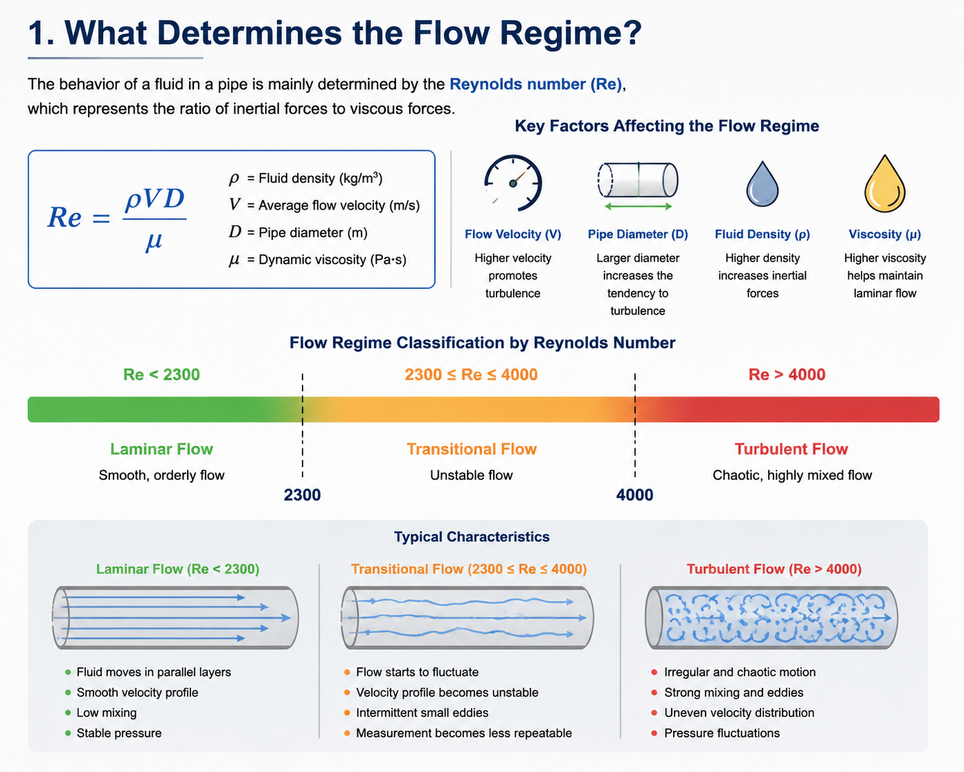
The behavior of a fluid inside a pipe is mainly determined by the Reynolds number (Re).
The Reynolds number represents the relationship between inertial forces and viscous forces in fluid flow:
Re=μρVD
Where:
- ρ = fluid density
- V = average flow velocity
- D = pipe diameter
- μ = dynamic viscosity
Generally:
| Reynolds Number | Flow Regime |
|---|---|
| Re < 2300 | Laminar Flow |
| 2300–4000 | Transitional Flow |
| Re > 4000 | Turbulent Flow |
The transition between these flow conditions directly affects velocity distribution, pressure stability, and flow measurement performance.
2. Three Common Flow Regimes Explained
1) Laminar Flow — Smooth and Organized
In laminar flow, fluid particles move in parallel layers.
The flow profile is stable, with little mixing between layers.
Typical characteristics:
- Smooth velocity distribution
- Low turbulence
- Stable pressure conditions
- Usually occurs at low velocity or with high-viscosity fluids
Laminar flow is common in:
- Hydraulic systems
- Lubrication systems
- High-viscosity oil applications
For instrumentation, the key point is:
A stable flow condition generally provides predictable measurement behavior.
However, not all industrial flow meters require laminar flow. Many industrial meters are designed to operate under fully developed turbulent flow.
2) Transitional Flow — The Most Unstable Region
Transitional flow exists between laminar and turbulent flow.
The fluid begins to develop fluctuations, but the flow is not fully turbulent yet.
This condition is often the most difficult for measurement because:
- Flow velocity changes irregularly
- The flow profile becomes unstable
- Measurement repeatability may decrease
Typical symptoms:
- Flow indication fluctuates slightly
- Measurements are sometimes accurate and sometimes incorrect
- Operators may mistakenly suspect instrument failure
Before replacing the instrument, engineers should check:
- Actual flow velocity
- Pipe size selection
- Valve position
- Upstream disturbances
- Straight pipe length
3) Turbulent Flow — Mixed and Highly Dynamic
In turbulent flow, fluid particles move randomly with strong mixing and eddies.
Characteristics include:
- Irregular velocity distribution
- Strong mixing
- Pressure fluctuations
- Swirling flow caused by fittings or equipment
Turbulent flow is very common in industrial processes.
It occurs in:
- Water pipelines
- Steam systems
- Chemical processes
- Compressed air systems
Importantly:
Turbulent flow is not always harmful.
Many industrial flow meters are designed to work under stable turbulent conditions.
For example:
- Electromagnetic flow meters
- Vortex flow meters
- Orifice flow meters
The real problem is not turbulence itself, but unstable and disturbed flow conditions.
3. How Flow Conditions Affect Flow Meter Performance
Different flow meter technologies have different requirements.
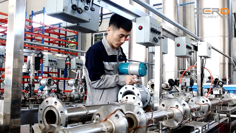
Electromagnetic Flow Meter
Electromagnetic flow meters require a stable velocity profile.
Common problems:
- Installation too close to elbows
- Pump outlet turbulence
- Air bubbles
- Poor grounding
Possible symptoms:
- Unstable output signal
- Incorrect flow indication
Solutions:
- Provide sufficient straight pipe length
- Install flow conditioners when necessary
- Avoid installation near strong disturbances
Vortex Flow Meter
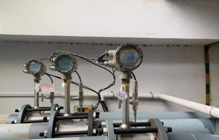
Vortex meters rely on vortex shedding behind a bluff body.
They require:
- Stable velocity distribution
- Proper upstream and downstream piping
Problems caused by poor flow conditions:
- Output fluctuation
- Incorrect frequency detection
Differential Pressure Flow Meter (Orifice Plate)
Orifice flow measurement depends on a predictable pressure difference.
Improper flow conditions may cause:
- Incorrect differential pressure
- Measurement deviation
- Poor repeatability
Ultrasonic Flow Meter
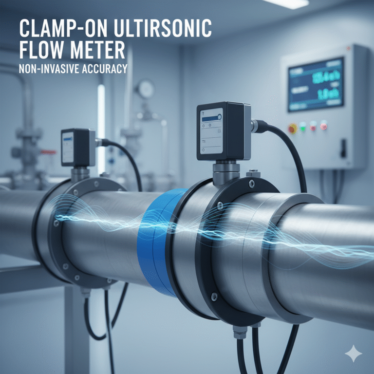
Ultrasonic flow meters are sensitive to velocity distribution.
Common issues:
- Swirling flow
- Asymmetric velocity profile
- Incorrect sensor installation
4. Why Straight Pipe Length Matters
Many engineers know that flow meters require straight pipe sections, but the reason is often misunderstood.
The purpose of straight pipe length is:
To allow disturbed flow to recover into a more stable velocity profile before measurement.
Sources of flow disturbance include:
- Elbows
- Control valves
- Pumps
- Reducers and expanders
- Tees
Without sufficient straight pipe length, the meter may measure a distorted flow profile instead of the true average flow.
5. How to Troubleshoot Flow Measurement Problems
When a flow meter shows abnormal readings, do not immediately assume the instrument is damaged.
A better troubleshooting approach:
Step 1: Check Process Conditions
Confirm:
- Flow velocity
- Pipe size
- Medium properties
- Pressure and temperature
- Valve operation
Step 2: Check Installation Conditions
Inspect:
- Straight pipe length
- Pipe alignment
- Sensor installation
- Grounding
- Air bubbles or vibration
Step 3: Check the Instrument
Only after confirming the process condition should you check:
- Sensor condition
- Wiring
- Configuration parameters
- Calibration status
6. The Key Lesson for Instrument Engineers
Understanding flow regimes is not about memorizing fluid mechanics theory.
It is about solving real industrial problems.
A stable flow condition usually means:
- Better measurement repeatability
- Fewer false alarms
- Longer instrument lifetime
- Easier troubleshooting
When a flow meter shows abnormal behavior, always remember:
The problem may not be the instrument. The flow condition itself may be the real cause.

Conclusion
Laminar flow, transitional flow, and turbulent flow are fundamental concepts for every instrumentation engineer.
By understanding how fluid behavior affects measurement, engineers can make better decisions on:
- Flow meter selection
- Installation design
- Troubleshooting
- Preventive maintenance
A good instrument engineer does not only understand the meter — they also understand the fluid flowing through it.