Introduction
Turbine flow meters are widely used for measuring liquid and gas flow rates due to their high accuracy, reliability, and cost-effectiveness. These flow meters operate by utilizing a rotating turbine wheel placed in the path of the fluid, where the rotational speed is directly proportional to the velocity of the fluid. However, to ensure optimal performance, accuracy, and longevity, several key factors must be considered when using turbine flow meters. This article discusses the best practices for installation, operational considerations, maintenance, and troubleshooting to enhance the effectiveness of these devices.

1. Installation Considerations
Proper installation is crucial for achieving accurate and reliable readings from a turbine flow meter. Below are key factors to consider:
1.1 Proper Pipeline Configuration
Straight Pipe Requirements: To ensure laminar flow and avoid turbulence, install the flow meter in a straight section of the pipeline. Typically, a minimum of 10 pipe diameters (10D) of straight pipe upstream and 5D downstream is recommended.
Avoiding Flow Disturbances: Position the flow meter away from bends, valves, reducers, and pumps that may cause flow disturbances.
Flow Conditioners: If a long straight pipe section is unavailable, use a flow conditioner to help stabilize the fluid before it enters the flow meter.
1.2 Installation Orientation
Horizontal Installation: The preferred orientation for most turbine flow meters is horizontal, with the turbine shaft aligned parallel to the flow direction.
Vertical Installation: If vertical installation is necessary, ensure that the fluid flows from bottom to top to prevent errors caused by trapped air or sediment accumulation.
1.3 Protection from External Factors
Vibration and Mechanical Stress: Excessive vibration can affect the turbine’s movement, leading to inaccurate readings. Secure the pipeline to minimize vibrations.
Electromagnetic Interference (EMI): Turbine flow meters use magnetic or optical sensors that may be affected by nearby electrical equipment. Keep them away from power lines, motors, and transformers.
2. Operational Considerations
To maintain accuracy and efficiency, turbine flow meters must be used within their operational limits and under suitable conditions.
2.1 Flow Rate Considerations
Operating Within Rated Range: Ensure that the flow meter operates within the manufacturer’s specified range. Operating at very high or very low flow rates can reduce accuracy and wear down internal components.
Sudden Flow Changes: Avoid rapid pressure or flow rate fluctuations, as these can damage the turbine blades and bearings.
2.2 Fluid Properties
Clean Fluids: Turbine meters work best with clean fluids free of solid particles. If there is a risk of contamination, use an inline filter (typically 20–50 microns) to prevent debris from damaging the turbine.
Viscosity Considerations: Most turbine meters are calibrated for low-viscosity fluids. Higher viscosity can slow down the turbine’s response, leading to incorrect readings.
Temperature and Pressure Limits: Ensure the fluid temperature and pressure remain within the instrument’s rated range to avoid mechanical failure or measurement errors.
3. Maintenance and Calibration
Routine maintenance and calibration are essential for sustaining measurement accuracy and prolonging the flow meter’s lifespan.
3.1 Regular Cleaning
Periodically inspect and clean the turbine, as debris buildup or scaling can impede rotation.
If the flow meter is used in processes prone to sedimentation, schedule frequent cleanings to avoid measurement drift.
3.2 Calibration Procedures
Turbine flow meters should be calibrated at least once per year, depending on usage frequency and industry regulations.
Calibration can be done using a comparison method with a certified reference meter or by performing on-site verification with a known fluid volume.
3.3 Wear and Tear Inspection
Inspect turbine blades and bearings for signs of wear or deformation, as these components experience frictional forces over time.
Replace worn-out components as needed to maintain accurate measurements.
4. Troubleshooting Common Issues
Despite proper installation and maintenance, issues may still arise. The following table summarizes common problems and their solutions:
| Problem | Possible Causes | Solutions |
|---|---|---|
| No signal output | Faulty wiring, sensor damage, turbine blockage | Check electrical connections, clean turbine, inspect sensor |
| Erratic or fluctuating readings | Air bubbles, vibrations, flow disturbances | Install air eliminators, secure the pipeline, add flow conditioners |
| Overestimated flow rates | High fluid viscosity, excessive velocity, sensor malfunction | Verify fluid properties, check sensor calibration, slow down flow |
| Underestimated flow rates | Worn turbine blades, low flow velocity, debris accumulation | Inspect turbine blades, clean the system, increase flow rate |
5. Special Considerations for Gas Measurement
While turbine flow meters are primarily used for liquids, some models are designed for gas applications. When measuring gas flow:
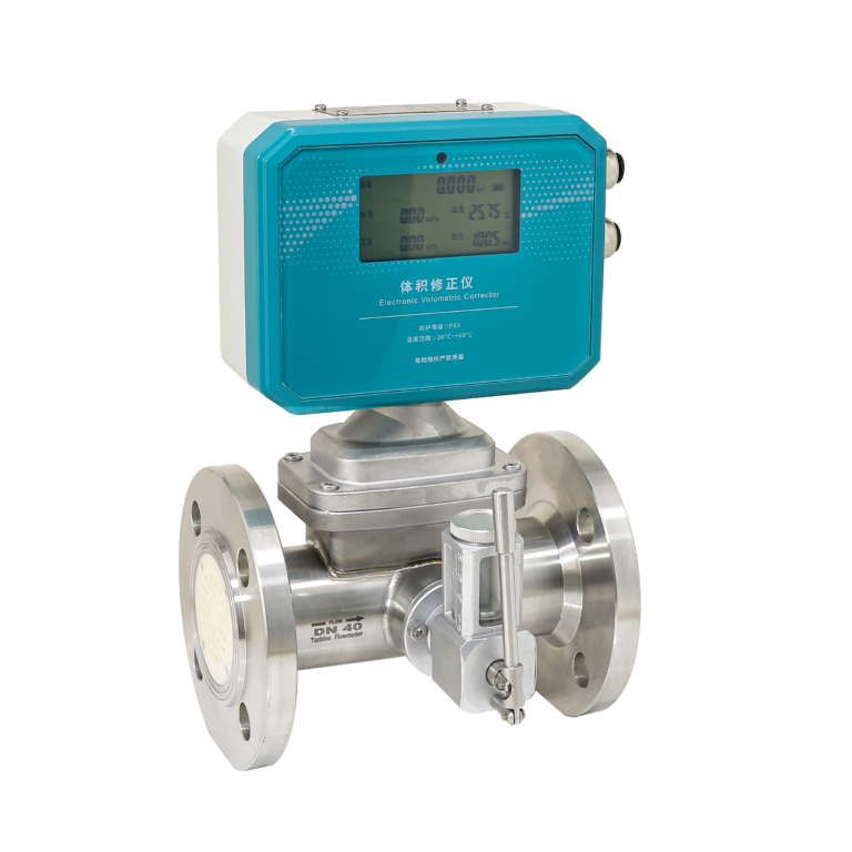
Pressure and Temperature Compensation: Ensure the system includes compensation for gas density variations due to changes in pressure and temperature.
Proper Sizing: Gas meters must be sized appropriately, as gas compressibility can impact turbine speed and measurement accuracy.
Conclusion
Turbine flow meters offer an accurate and reliable method for measuring fluid and gas flow rates. However, their performance largely depends on proper installation, correct operational practices, and regular maintenance. By ensuring a stable flow profile, using clean fluids, performing periodic calibrations, and troubleshooting issues promptly, users can maximize the efficiency and lifespan of their turbine flow meters. Whether applied in industrial, pharmaceutical, or petroleum sectors, these best practices ensure optimal measurement accuracy and system reliability.