Company: Dalian Zero Instrument Technology Co., Ltd. Document Type: Standard Operating Procedure (SOP) Effective Date: 18th Sep 2025 Version: V1.0
1. Scope
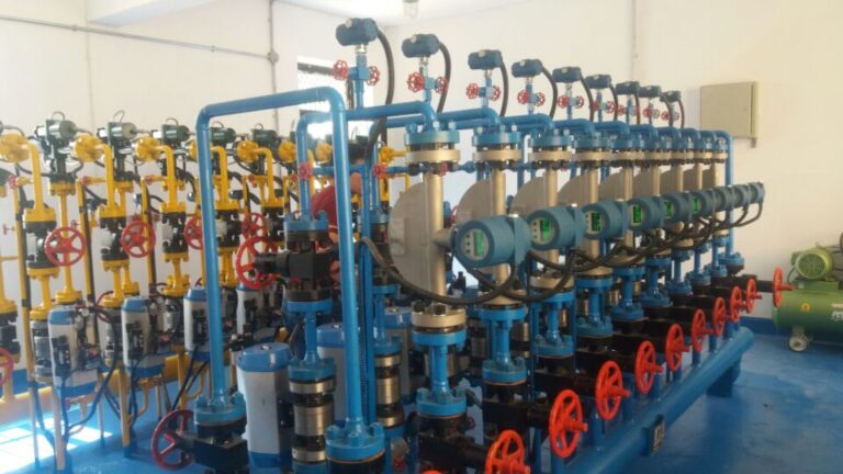
This document specifies the inspection, zero-point calibration, and maintenance procedures for common industrial instruments, including flowmeters, level transmitters, pressure transmitters, and valves. It is applicable to on-site commissioning, preventive maintenance, troubleshooting, and periodic inspection in chemical, petrochemical, power, and water treatment plants.
2. Safety Precautions
Ensure process shutdown and complete depressurization before inspection.
Obtain work permits for electrical isolation, gas cutting, or confined space entry.
Wear appropriate PPE: gloves, goggles, antistatic clothing, and safety shoes.
Avoid direct contact with process medium; purge and flush pipelines before operation.
Use calibrated tools and instruments within valid verification periods.
3. Reference Standards
IEC 61511 — Functional Safety: Safety Instrumented Systems
ISA RP55.1 — Instrument Calibration Practices
GB/T 21446 — Industrial Process Measurement Instruments
API 598 — Valve Inspection and Testing
ISO 15848 — Industrial Valves: Fugitive Emissions Testing
4. Flowmeter Zero-Point Inspection
4.1 Orifice Plate Flowmeter
Preparation:
Confirm pipeline is depressurized and medium drained.
Close upstream and downstream valves, open equalizing valve.
Prepare multimeter, communicator, and ensure tools are calibrated.
Procedure:
Connect communicator to transmitter.
Verify output signal at 4mA (±0.02mA).
If deviation exists, initiate zero calibration via communicator.
Confirm stable zero reading after 5–10 minutes.
Close equalizing valve, reopen process valves, observe stability.
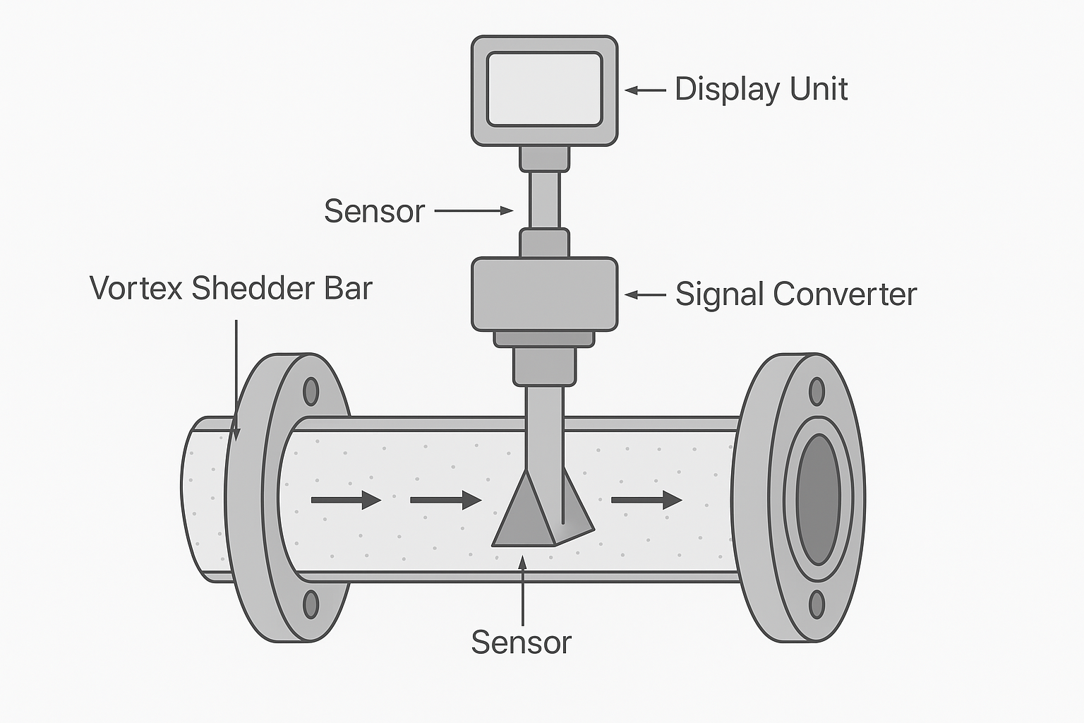
4.2 Vortex Flowmeter
Conditions:
Medium must be static, pipeline vibration <5Hz, amplitude <0.1mm.
Power supply stable (220V ±10% or 24V ±5%).
Procedure:
Enter calibration mode via local button or software.
Select “Static Zero Calibration,” collect signal for 30–60s.
Eliminate installation stress or probe contamination if errors occur.
Save parameters, reopen valves, confirm reading starts from zero.
4.3 Coriolis Mass Flowmeter
Preparation:
Bypass medium, confirm no residual flow (<0.01kg/h).
Verify horizontal installation, release stress if detected.
Preheat sensor (30–120 minutes depending on type).
Procedure:
Enter “Zero Calibration” menu (liquid or gas mode).
Ensure no vibration; start calibration program.
Acceptable zero error: ±0.02% FS.
Compare with reference flowmeter under operating conditions.
5. Level Transmitter Zero-Point Inspection
5.1 Differential Pressure (DP) Level Transmitter
Close impulse valves, open equalizing valve.
Verify output at 4mA (±0.02mA).
Adjust “Zero Offset” if required.
Reopen valves, compare with local gauge; deviation ≤ ±1mm.
5.2 Radar Level Transmitter
Ensure tank empty, no vapor or dust interference.
Clean antenna, adjust angle perpendicular to surface.
Verify “Empty Distance” equals full measuring range.
Calibrate zero point; output should be 4mA (±2mm).
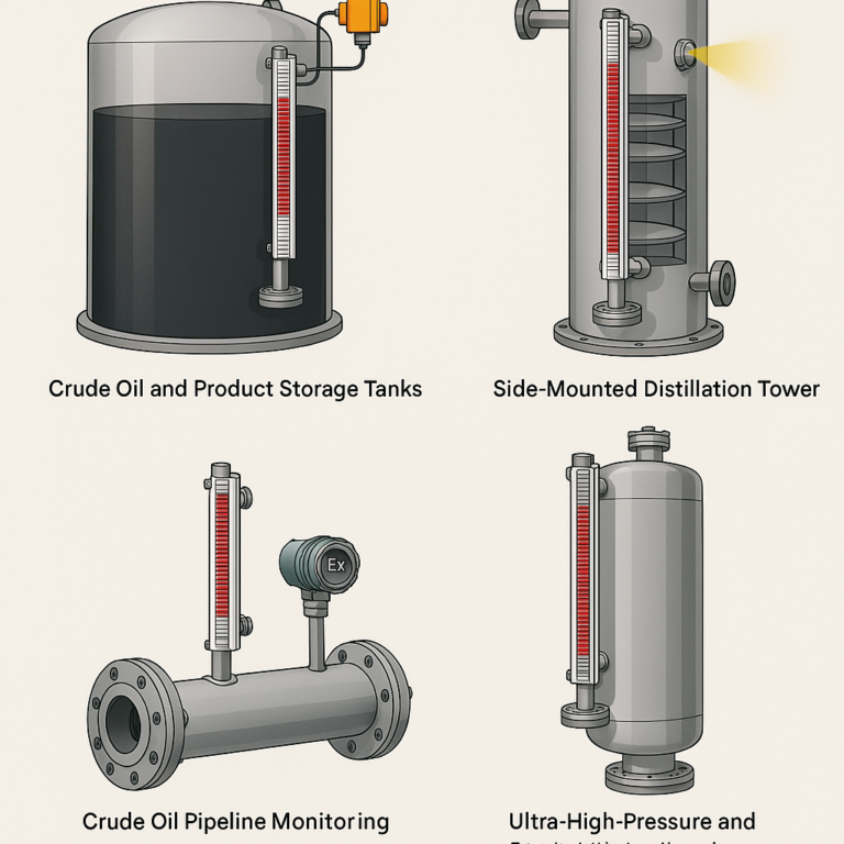
5.3 Magnetic Level Gauge
Confirm float at “empty” position, check scale alignment.
Adjust panel zero mark to float position (tolerance ±1mm).
Refill tank slowly, confirm continuous and accurate color change.
6. Pressure Transmitter Zero-Point Inspection
6.1 General Preparation
Isolate pressure source, drain or vent chamber.
Verify power supply and wiring.
6.2 Method
Gauge Pressure Transmitter: Output = 4mA at atmospheric pressure.
Absolute Pressure Transmitter: Apply reference atmospheric pressure with calibrator.
Differential Pressure Transmitter: Open equalizing valve, confirm output = 4mA.
Adjustment:
Use zero adjustment screw or communicator “Manual Zero” function.
Wait 10 minutes; confirm stability within ±0.02mA.
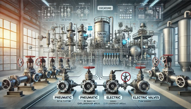
7. Valve Inspection
7.1 Stroke Check
Use ruler/dial gauge to measure actual travel.
Compare with rated stroke; tolerance ≤ ±1%.
Check limit switches for full-open/full-close positions.
7.2 Opening/Closing Time Test
Measure with timer (accuracy 0.01s).
Record average of 3 cycles.
Compare with historical records; deviation >20% requires investigation.
7.3 Leakage Test
Liquid Valves: Pressure drop or collection method; acceptable leakage <1% rated pressure.
Gas Valves: Bubble test or pressure decay method.
Test pressure = 1.05–1.1 × rated working pressure.
7.4 Valve Disassembly and Inspection
Obtain work permits, isolate process lines.
Use proper tools and torque wrench; follow cross-tightening principle.
Inspect valve core/seat for wear, corrosion, cracks (tolerance ≤0.1mm).
Minor wear: lap with polishing paste.
Severe wear: replace valve core and seals.
8. Documentation and Records
Maintain calibration/inspection logs including:
Instrument ID, type, location.
Test method, measured values, adjustments.
Technician name, date, remarks.
Compare with historical data to evaluate performance trends.
Archive in CMMS or maintenance management system.
✅ Conclusion: This SOP ensures that flowmeters, level transmitters, pressure transmitters, and valves maintain reliable zero-point accuracy and mechanical integrity, reducing failure risk and ensuring process safety.