
PE vs Functional Grounding vs Shield Grounding – A Practical Engineering Guide
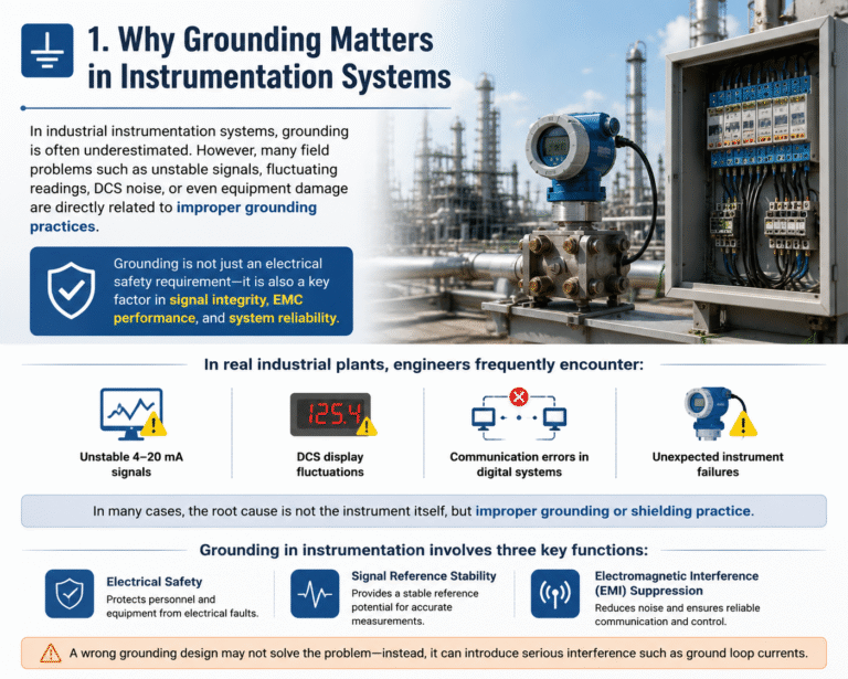
In industrial instrumentation systems, grounding is often underestimated. However, many field problems such as unstable signals, fluctuating readings, DCS noise, or even equipment damage are directly related to improper grounding practices.
Grounding is not just an electrical safety requirement—it is also a key factor in signal integrity, EMC performance, and system reliability.
A wrong grounding design may not solve the problem—instead, it can introduce serious interference such as ground loop currents.
1. Why Grounding Matters in Instrumentation Systems
In real industrial plants, engineers frequently encounter:
- Unstable 4–20 mA signals
- DCS display fluctuations
- Communication errors in digital systems
- Unexpected instrument failures
In many cases, the root cause is not the instrument itself, but improper grounding or shielding practice.
Grounding in instrumentation involves three key functions:
- Electrical safety
- Signal reference stability
- Electromagnetic interference (EMI) suppression
2. Three Types of Grounding in Industrial Systems
Industrial grounding can be divided into three categories:
2.1 Protective Earth (PE)
Purpose: Personnel and equipment safety
Protective grounding connects all exposed metallic enclosures (instrument housings, cabinets, junction boxes) to earth.
If insulation failure occurs, fault current is safely diverted to ground, triggering protective devices such as circuit breakers or RCDs.
Key characteristics:
- Typical resistance requirement: ≤ 4 Ω (low-voltage systems)
- Conductor color: Green/Yellow
- Grounding conductor size: Typically 1.5–2.5 mm² for instruments
- Must never carry signal current
👉 Important:
PE conductors must never be used as signal reference paths. Leakage or stray current may cause measurement errors.
2.2 Functional Ground (Signal Ground / Instrument Ground)
Purpose: Provide a stable reference potential for signal systems
Functional grounding ensures that all analog and digital signals share a unified reference point.
It is commonly used in DCS systems, PLC systems, and control cabinets.
Key characteristics:
- Typical resistance requirement: ≤ 1 Ω (instrument grounding network)
- Used for 24 VDC return reference (system dependent)
- Must be separated from PE inside control cabinets
- Connected to a unified plant grounding grid
👉 In modern systems:
Most 24 VDC systems operate with either:
- Floating negative (preferred in modern industrial systems), or
- Ground-referenced negative (legacy systems)
2.3 Shield Ground (Cable Shielding Ground)
Purpose: Suppress electromagnetic interference (EMI)
Cable shielding is used to prevent external electromagnetic noise from coupling into signal conductors.
However, incorrect grounding of shields is one of the most common sources of noise issues.
🔸 Low-frequency analog signals (4–20 mA, RTD, thermocouple)
✔ Shield must be grounded at one end only (DCS side)
✔ Field side must remain floating
Why?
Because grounding both ends creates a ground loop, which allows circulating current to flow through the shield, generating 50 Hz interference.
🔸 High-frequency digital signals (Ethernet, PROFIBUS, FOUNDATION Fieldbus)
✔ Shield must be grounded at both ends (360° termination)
Why?
High-frequency systems require low-impedance paths to earth to ensure EMC compliance.
3. Why Double-End Shield Grounding Causes Noise
Industrial grounding systems are never perfectly equipotential.
Due to motors, transformers, and lightning protection systems, different grounding points may have voltage differences ranging from millivolts to several volts.
When both ends of a shield are grounded:
Shield → Ground A → Earth Grid → Ground B → Shield
This forms a closed loop, and loop current is generated:
I = ΔV / R
This current induces electromagnetic fields, which couple into signal conductors and introduce 50 Hz noise or unstable readings.
4. Comparison of Grounding Types
| Item | Protective Earth (PE) | Functional Ground | Shield Ground |
|---|---|---|---|
| Purpose | Safety protection | Signal reference | EMI suppression |
| Object | Equipment housing | Signal return / 24V reference | Cable shield |
| Connection | Local grounding | Single-point grounding system | DCS-side grounding (analog) |
| Resistance | ≤ 4 Ω | ≤ 1 Ω | ≤ 1 Ω (system dependent) |
| Wiring Color | Green/Yellow | Black / Blue (system defined) | Cable shield |

5. Grounding Architecture in DCS Systems
Modern DCS systems (Honeywell, Siemens, ABB, Emerson) adopt a single-point grounding philosophy:
- Separate internal grounding buses
- Unified plant grounding grid
Typical structure:
- Plant Ground Grid
- PE Ground Bus (equipment safety)
- Instrument Ground Bus (signal reference)
- Shield Ground Bus (EMC control)
All eventually connect to the same grounding network, but remain electrically separated inside control cabinets.
6. Practical Field Applications
6.1 Pressure Transmitters (2-wire systems)
- Housing → PE grounding
- Signal loop → independent from PE
- Cable shield → grounded at DCS side only
6.2 Thermocouples (strong EMI environments)
- Sensor sheath: usually isolated from ground
- Shield: single-end grounding only
- Use differential input for noise rejection
6.3 Intrinsically Safe Systems
For Zener barriers:
- Safety barrier enclosure → PE grounding
- Intrinsic safety ground → dedicated IS ground bar
⚠️ These two must never be mixed.
6.4 Long-distance signal transmission (>500 m)
- Install surge protection devices (SPD)
- Ground SPD housing to PE
- Maintain shield single-end grounding for analog signals
7. Key Engineering Principles
Modern standards (IEC 61000-5-2, IEC 60364, ISA guidelines) emphasize:
✔ “Single-point grounding + system-level equipotential bonding”
Key rules:
- PE, signal ground, and shield ground must be separated inside cabinets
- All grounding systems ultimately connect to a unified plant grounding grid
- Never use multiple independent grounding electrodes for instrumentation systems
- Avoid ground loops at all costs
8. Common Engineering Mistakes
❌ Mistake 1: Shield grounded at both ends (analog signals)
→ Causes ground loop current and 50 Hz noise
❌ Mistake 2: Mixing PE and signal ground
→ Introduces leakage current into measurement system
❌ Mistake 3: Independent grounding rods for instruments
→ Creates potential difference and instability

9. Conclusion
Proper grounding design in industrial instrumentation is essential for:
- Electrical safety (PE)
- Signal stability (Functional Ground)
- EMC protection (Shield Ground)
Although these three systems serve different purposes, they must follow strict separation rules while ultimately connecting to a unified plant grounding network.
Incorrect grounding design is one of the most common root causes of unstable instrumentation signals in industrial plants.