Understanding Analog Signals in PLC Systems
In industrial automation, Programmable Logic Controllers (PLCs) play a crucial role in monitoring and controlling processes. However, most real-world signals, such as temperature, pressure, and flow rate, are continuous analog signals. PLCs, on the other hand, operate using digital signals (binary 0s and 1s). This means that analog signals must be converted into a form that PLCs can understand before being processed.
This article will guide you through how analog signals are input into PLCs and transformed into actionable control commands.
What Is an Analog Signal?
An analog signal is a continuous signal that can take on an infinite number of values within a given range. A good example is temperature measured by a thermometer, which varies smoothly over time. In contrast, digital signals are discrete, meaning they only have specific values, usually represented as binary numbers.
Common analog signals in industrial applications include:
Temperature: From thermocouples or RTDs (Resistance Temperature Detectors)
Pressure: Measured by pressure sensors
Flow Rate: Provided by flow meters
Level: From liquid level sensors
Since PLCs operate in the digital domain, they need a way to interpret these continuously changing signals.
The Conversion Process: From Analog to PLC-Readable Signals
Step 1: Capturing Analog Signals with Sensors
A sensor acts as the “ears” of the PLC system, detecting physical properties such as temperature, pressure, or flow. However, raw sensor signals are often weak and not standardized. To ensure accurate and reliable transmission, a transmitter is used.
Step 2: Signal Conditioning with Transmitters
A transmitter acts as a “translator,” taking the weak electrical signal from the sensor and converting it into a standardized format suitable for transmission to the PLC. The two most common types of analog signals used in industrial automation are:
4-20mA Current Signal:
4mA represents the minimum measurable value.
20mA represents the maximum measurable value.
Offers strong resistance to electrical noise and long-distance transmission capabilities.
0-10V Voltage Signal:
0V represents the minimum measurable value.
10V represents the maximum measurable value.
Easier to implement but more susceptible to electrical interference.
Since current signals (4-20mA) are less affected by resistance and voltage drops over long distances, they are preferred in industrial applications.
How Does the PLC Receive Analog Signals?
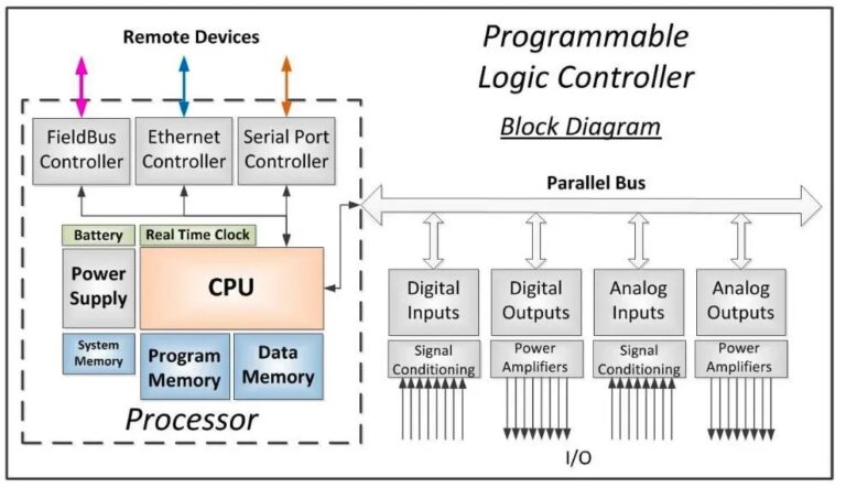
Step 3: Analog Input Module in PLCs
Once the conditioned signal reaches the PLC, it must be processed by the Analog Input Module (AIM). This module acts as the “receiver” of the PLC, performing several crucial functions:
Electrical Isolation: Protects the PLC from voltage spikes and noise.
Signal Conditioning: Ensures signal stability and improves measurement accuracy.
Analog-to-Digital Conversion (ADC): Converts the continuous analog signal into a discrete digital value that the PLC can process.
The resolution of the ADC is an important factor in determining the accuracy of the measurement. A 12-bit ADC can divide an analog input range (e.g., 0-10V) into 4,096 discrete steps (2^12), providing finer resolution than a 10-bit ADC (which has only 1,024 steps). Higher resolution results in more precise control.
Step 4: Data Processing and Control Decisions
Once the analog signal has been digitized, it is sent to the PLC’s Central Processing Unit (CPU). The CPU uses pre-programmed logic to process the data and make decisions.
For example, in a boiler temperature control system:
A temperature sensor detects the current temperature.
The sensor’s signal is converted into a 4-20mA current.
The PLC receives the current via its Analog Input Module and converts it to a numerical value.
The CPU compares the value against a set threshold and determines whether the burner should be turned on or off.
This process happens continuously, ensuring precise and automatic control.

Choosing and Maintaining the Right Components
To ensure accurate and reliable analog input processing, selecting the right components is crucial. Here are some key factors to consider:
1. Selecting the Right Sensors and Transmitters
Choose sensors that are suitable for the environment (e.g., waterproof sensors for humid areas).
Ensure transmitters are compatible with PLC input specifications.
2. Using the Proper Analog Input Module
Check the input type (current or voltage) and resolution (bit depth) before purchasing.
Use isolated modules to prevent interference from external electrical noise.
3. Regular Calibration and Maintenance
Periodically calibrate sensors and transmitters to maintain accuracy.
Inspect wiring and connections to prevent signal degradation due to corrosion or loose terminals.
Common Questions and Issues
1. Why is 4-20mA preferred over 0-10V?
4-20mA is less affected by electrical noise and voltage drops over long distances, making it more reliable in industrial environments.
2. How do I check if my PLC is receiving the correct analog input?
Most PLCs provide diagnostic tools to monitor real-time input values. Check the PLC’s software or use a multimeter to verify the signal.
3. What happens if the sensor fails?
Many systems implement fail-safe mechanisms, such as setting a default safe value or triggering an alarm if the signal falls below 4mA

Common Questions and Issues
1. Why is 4-20mA preferred over 0-10V?
4-20mA is less affected by electrical noise and voltage drops over long distances, making it more reliable in industrial environments.
2. How do I check if my PLC is receiving the correct analog input?
Most PLCs provide diagnostic tools to monitor real-time input values. Check the PLC’s software or use a multimeter to verify the signal.
3. What happens if the sensor fails?
Many systems implement fail-safe mechanisms, such as setting a default safe value or triggering an alarm if the signal falls below 4mA.
Conclusion
The process of bringing an analog signal into a PLC involves multiple steps: capturing the signal with sensors, conditioning it with transmitters, converting it into a digital format via an analog input module, and finally, processing the data in the PLC’s CPU. By understanding this process, engineers and technicians can optimize automation systems for better accuracy, efficiency, and reliability.
Regular maintenance, proper component selection, and understanding signal characteristics are key to ensuring smooth operation in industrial automation.
By mastering these concepts, you can effectively integrate and troubleshoot analog inputs in your PLC systems, improving process control and efficiency in your applications.