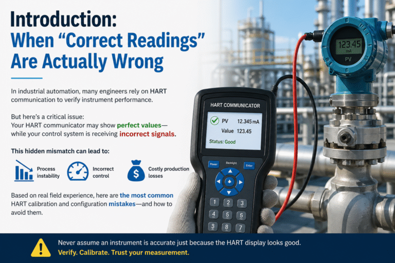
Introduction: When “Correct Readings” Are Actually Wrong
In industrial automation, many engineers rely on HART communication to verify instrument performance.
But here’s a critical issue: 👉 Your HART communicator may show perfect values — while your control system is receiving incorrect signals.
This hidden mismatch can lead to:
Process instability
Incorrect flow/pressure control
Costly production losses
Based on real field experience, here are the most common HART calibration and configuration mistakes — and how to avoid them.
⚠️ Mistake #1: Believing Digital Values Replace Physical Calibration
Many users assume: “If the HART value is correct, the instrument must be accurate.”
❌ This is not true
👉 HART instruments fundamentally rely on the 4–20 mA analog signal 👉 The digital value is calculated internally — but the control system reads the current loop
Real Risk:
Analog drift → DCS receives wrong signal
Digital value still looks normal
✔ Best Practice:
Always calibrate the 4–20 mA input/output loop using a standard signal source
Never rely on digital values alone
⚠️ Mistake #2: Confusing Process Variables with Output Variables
HART devices can handle multiple variables:
PV (Primary Variable)
SV (Secondary Variable)
TV / QV
Output Current Variable
👉 A common mistake: Changing PV or SV without updating the output mapping
Result:
Display value changes
But 4–20 mA output does NOT change
✔ Best Practice:
Verify dynamic variable mapping
Ensure the correct variable is assigned to the current output
⚠️ Mistake #3: Ignoring Loop Resistance During Online Calibration
When connecting a HART communicator without breaking the loop:
👉 The loop must meet this condition:
250 – 1100 Ω resistance
What happens if not?
Condition
Result
< 250 Ω
Communication failure
> 1100 Ω
Signal instability
✔ Best Practice:
Check total loop resistance:
Safety barriers
I/O cards
Cables
Add resistor if required
⚠️ Mistake #4: High Damping Setting During Calibration
Damping is used to smooth noisy signals.
👉 But during calibration:
High damping = slow response
Reading takes too long to stabilize
Result:
Calibration delay
Incorrect recorded values
✔ Best Practice:
Set damping to 1–2 seconds during calibration
Restore normal value after calibration
⚠️ Mistake #5: Relying Only on Digital Diagnostics
Modern HART devices provide:
Sensor health status
Error logs
Communication diagnostics
👉 But here’s the problem:
❗ These diagnostics do NOT detect early accuracy drift
Real Risk:
Instrument gradually becomes inaccurate
No alarm is triggered
✔ Best Practice:
Maintain periodic calibration schedule
Combine:
Time-based calibration
Performance-based verification
⚠️ Mistake #6: Using Non-HART-Compatible Safety Barriers
In hazardous areas (Ex zones):
👉 Not all safety barriers support HART signals
Common Issue:
Barrier filters out digital signal
HART communication fails
✔ Best Practice:
Before installation, verify compatibility of:
Transmitter
Safety barrier
Isolator
DCS I/O card
✅ Final Thought: HART Is Powerful — But Only When Used Correctly
HART technology is extremely useful, but only when:
✔ Analog signals are properly calibrated ✔ Variables are correctly mapped ✔ Loop conditions are verified ✔ System compatibility is ensured
👉 Ignoring these factors can silently reduce your measurement accuracy — without obvious alarms.
🚀 Need Reliable HART Instruments or Technical Support?