
The HART 475 Field Communicator has been widely used by instrumentation technicians and maintenance engineers to configure, diagnose, and troubleshoot smart field instruments.
From pressure transmitters and temperature sensors to electromagnetic flowmeters, vortex flowmeters, Coriolis mass flowmeters, and radar level transmitters, HART communication provides access to valuable device information that cannot always be obtained from a conventional 4–20 mA signal.
However, using a HART communicator correctly requires more than knowing which buttons to press.
Incorrect configuration, inappropriate calibration, communication problems, and misunderstood diagnostic messages can lead to inaccurate measurements, unexpected control-system behavior, or unnecessary instrument replacement.
This practical guide explains common HART 475 functions, configuration terminology, troubleshooting methods, and important precautions for industrial field applications.
Important: Menu structures and diagnostic messages vary by manufacturer, device model, firmware version, HART revision, and installed Device Description (DD). The examples below are engineering references rather than universal menu sequences. Always follow the appropriate manufacturer’s documentation.
1. What Is the HART 475 Field Communicator?
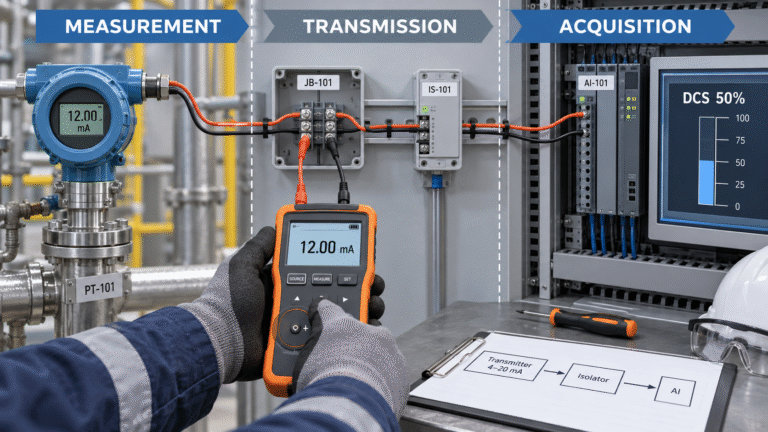
The Emerson 475 is a handheld configuration and diagnostic device designed to communicate with compatible HART and FOUNDATION Fieldbus instruments.
For HART instruments, it enables technicians to access digital information through the instrument’s communication interface, typically alongside the conventional 4–20 mA analog signal.
Common functions include:
- Reading process variables and device status.
- Checking instrument model, tag, and firmware information.
- Configuring measurement units and output ranges.
- Adjusting damping and selected application parameters.
- Performing loop tests and permitted calibration procedures.
- Reading diagnostic messages and device alerts.
- Identifying sensor, electronics, and configuration problems.
Is the HART 475 Still Supported?
The 475 Field Communicator is a discontinued product. Emerson ended factory support and new DD updates in October 2020.
Existing units can still be useful for compatible instruments, particularly in facilities with established HART equipment.
However, newer transmitters may require updated device descriptions that are unavailable on a legacy 475.
For newer installations, maintenance teams should verify compatibility or consider a currently supported communicator such as the Emerson AMS Trex.
2. Understanding HART Communication Before Troubleshooting
HART stands for Highway Addressable Remote Transducer.
It allows digital information to be exchanged with compatible smart instruments, typically using frequency-shift-keyed signals superimposed on a conventional analog current loop.
The digital communication signal is designed not to disturb the average analog measurement current.
2.1 HART Loop Resistance
A conventional HART communication loop typically requires sufficient AC impedance for reliable communication.
A resistance of approximately 250 Ω is commonly used, although the acceptable load range depends on the transmitter, power supply, loop components, and communication equipment.
A separate resistor is not always necessary.
For example, some PLC and DCS analog input modules already provide suitable input impedance.
Before adding resistance:
- Review the transmitter’s HART wiring diagram.
- Confirm whether the analog input module provides the required communication impedance.
- Calculate the available loop voltage under operating conditions.
- Check whether additional resistance would cause insufficient transmitter terminal voltage.
- Verify the communicator connection points.
Field warning: Do not automatically add a 250 Ω resistor whenever communication fails. Unnecessary resistance can reduce the available voltage and create additional problems.
2.2 Device Descriptions and Compatibility
A Device Description, or DD, defines how a communicator interprets the supported configuration parameters, menus, and diagnostic information of a particular instrument.
When the corresponding DD is unavailable, the communicator may provide only limited generic HART functions.
Typical compatibility symptoms include:
- Unknown device identification.
- Missing configuration parameters.
- Incomplete diagnostic menus.
- Unsupported device-specific commands.
- Differences between the displayed menu and the manufacturer’s manual.
Before concluding that a transmitter is defective, verify the device model, firmware revision, and communicator DD compatibility.
3. Common HART 475 Menu Terms Explained
Although menu structures differ between manufacturers, many HART devices use similar terminology.
| Menu Term | Function |
|---|---|
| Device Information | Displays model, tag, serial number, and firmware information |
| Process Variables | Displays measured values and supported secondary variables |
| Basic Setup | Configures fundamental measurement settings |
| Detailed Setup | Provides extended application and output parameters |
| LRV / URV | Lower and upper range values |
| Damping | Adjusts measurement response filtering |
| Sensor Trim | Corrects sensor measurement characteristics using specified references |
| Analog Output Trim | Adjusts the correspondence between commanded and measured output current |
| Loop Test | Forces an output for testing, where supported |
| Diagnostics | Displays instrument condition and diagnostic alerts |
| Simulation | Simulates selected variables or outputs |
| Reset | Performs a defined reset function, depending on device support |
These terms describe common functions, not guaranteed menu locations.
Understanding LRV and URV
For a pressure transmitter configured from 0 to 10 bar:
- LRV = 0 bar
- URV = 10 bar
- 4 mA represents 0 bar
- 20 mA represents 10 bar
Under normal linear output configuration, 5 bar corresponds to 12 mA.
Changing LRV or URV modifies the configured measurement-to-output relationship. It does not automatically recalibrate the sensor.
This distinction is essential when troubleshooting transmitter accuracy.
4. Pressure Transmitter Configuration and Diagnostics
Pressure and differential pressure transmitters are among the most common instruments serviced with HART communicators.
Typical examples include Yokogawa EJA/EJX and Rosemount 3051 transmitters.
4.1 Rosemount 3051 Pressure Transmitters
Depending on the model and DD revision, available functions may include:
- Pressure measurement and process variable monitoring.
- Measurement range configuration.
- Engineering unit selection.
- Damping adjustment.
- Sensor zero trim.
- Analog output trim.
- Loop testing.
- Sensor and electronics diagnostics.
Common diagnostic categories include sensor failure, electronics failure, configuration errors, and process conditions outside operating limits.
Pressure Measurement Is Incorrect
Start by comparing the displayed digital pressure value with a known reference pressure.
If the digital measurement is incorrect, investigate:
- Reference pressure and test equipment accuracy.
- Impulse line blockage or leakage.
- Transmitter installation and orientation.
- Zero shift.
- Incorrect sensor configuration.
- Operating conditions outside the sensor limits.
Do not immediately perform a zero trim.
First determine whether the problem comes from the process connection, sensor measurement, or analog output.
Digital PV Is Correct but DCS Reading Is Incorrect
If the HART digital measurement is correct but the DCS indication is wrong, investigate the signal chain.
Check:
- LRV and URV configuration.
- Analog output scaling.
- DCS input range and engineering-unit scaling.
- Loop current measured with suitable equipment.
- Wiring and circuit integrity.
- Output simulation or loop test status.
An analog output trim may be appropriate only when a verified current-output calibration error has been established.
4.2 Yokogawa EJA and EJX Transmitters
Yokogawa pressure transmitters support various diagnostics and configuration functions depending on the specific model and communication version.
Typical troubleshooting includes checking sensor-related alarms, amplifier or electronics faults, out-of-range conditions, and invalid configuration settings.
For differential pressure installations, also inspect:
- High-pressure and low-pressure impulse lines.
- Manifold valve positions.
- Condensate levels in steam applications.
- Process static pressure.
- Differential pressure measurement range.
- Square-root output configuration, where applicable.
A partially blocked impulse line can produce misleading readings even when the transmitter electronics are functioning correctly.
Engineering tip: Always distinguish a transmitter fault from an impulse-line or process installation problem before replacing electronic components.
5. Temperature Transmitter Configuration and Troubleshooting
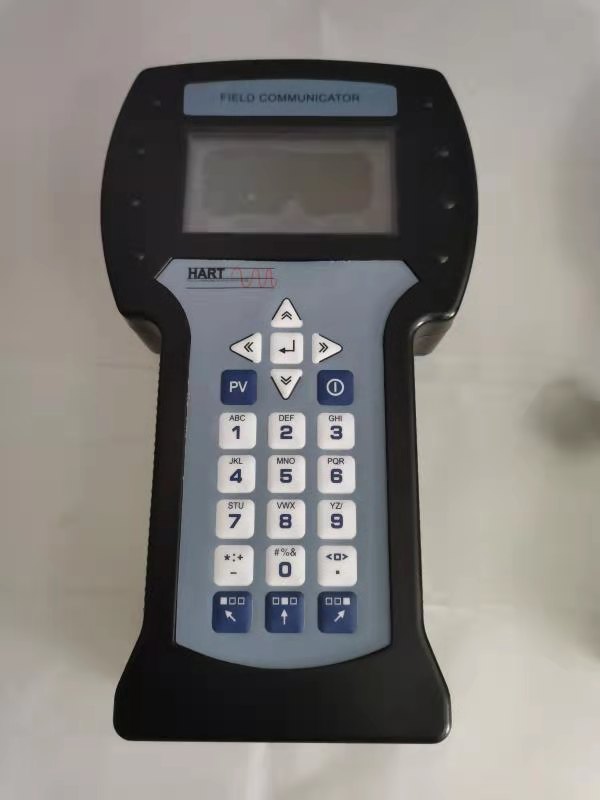
HART temperature transmitters allow technicians to configure sensor characteristics and diagnose common electrical problems.
Examples include supported Rosemount temperature transmitters and Endress+Hauser TMT-series instruments.
5.1 Check Sensor Type First
Incorrect sensor selection is a frequent cause of measurement errors.
Verify whether the connected element is:
- Pt100 or another resistance temperature detector (RTD).
- Thermocouple Type K, J, T, or another supported type.
- A two-wire, three-wire, or four-wire RTD connection.
For thermocouples, confirm the relevant cold-junction compensation configuration and correct thermocouple wiring.
For RTDs, confirm that the selected wiring configuration matches the installed sensor.
5.2 Common Temperature Measurement Problems
Open-circuit alarm
Inspect terminal connections, cable continuity, sensor condition, and junction-box wiring.
Short-circuit alarm
Check for damaged insulation, shorted conductors, or sensor element damage.
Unexpected temperature offset
Verify the configured sensor type, wiring arrangement, extension cable suitability, and reference measurement conditions.
Output remains at a fixed value
Check whether the transmitter is in simulation mode, whether a fault output is active, or whether the measured temperature has exceeded its configured operating limits.
Numerical diagnostic identifiers should always be interpreted using the specific transmitter’s manual. The same code cannot be assumed to have the same meaning across different product generations.
6. Electromagnetic Flowmeter Configuration and Diagnostics
Electromagnetic flowmeters measure the flow of electrically conductive liquids using Faraday’s law of electromagnetic induction.
HART-enabled transmitters may provide access to configuration, output testing, and diagnostic functions.
The Rosemount 8732 is one example.
6.1 Flowmeter Shows Zero Despite Actual Flow
Possible causes include:
- Empty or partially filled measuring pipe.
- Insufficient liquid conductivity.
- Incorrect wiring between sensor and transmitter.
- Electrode coating or contamination.
- Low-flow cutoff set too high.
- Incorrect flow direction configuration.
- Actual flow below the measurable operating range.
The first step is to confirm that the pipe is completely filled under the specified operating conditions.
Then check the digital flow value, output current, and active diagnostic messages.
6.2 Empty Pipe Detection
Some electromagnetic flowmeters provide empty pipe detection to identify conditions in which the measuring electrodes are not adequately wetted.
Empty pipe alarms can also be influenced by conductivity, electrode contamination, wiring, and installation conditions.
Avoid changing empty-pipe detection thresholds without reviewing the manufacturer’s recommended procedure.
Increasing or decreasing a threshold without understanding the diagnostic logic can mask an installation problem.
6.3 Unstable Flow Readings
Investigate the following:
- Poor grounding or potential equalization.
- Air bubbles or partially filled piping.
- Electrical interference.
- Incorrect cable routing.
- Electrode contamination.
- Unstable process flow.
- Inappropriate damping or filtering.
Signal damping can reduce displayed fluctuations, but it cannot correct a genuine hydraulic or installation problem.
7. Vortex Flowmeter Configuration and Diagnostics
Vortex flowmeters detect flow by measuring the frequency of vortices generated downstream of a bluff body.
Typical HART-enabled examples include the Rosemount 8600D and 8800D series, as well as compatible Endress+Hauser vortex transmitters.
7.1 Important Configuration Parameters
Depending on the instrument design, technicians may encounter:
- Engineering flow units.
- Flow range configuration.
- Reference K-factor.
- Low-flow cutoff.
- Damping and signal processing.
- Fluid or density settings.
- Pulse output scaling.
- Diagnostic and simulation functions.
The K-factor is particularly important because it relates the detected vortex frequency to the flow calculation.
Do not change a factory K-factor merely to force the displayed reading to match an expected process value.
Any correction must follow the manufacturer’s calibration and configuration procedure.
7.2 Flow Exists but the Meter Indicates Zero
Check the actual operating flow against the meter’s specified minimum measurable flow.
Also investigate:
- Incorrect mounting or flow direction.
- Excessive pipe vibration.
- Insufficient upstream or downstream straight pipe.
- Unstable or pulsating flow.
- Incorrect fluid settings.
- Excessive low-flow cutoff.
- Sensor or electronics faults.
For gas and steam applications, verify operating pressure, temperature, and density assumptions where applicable.
7.3 Excessive Vibration
Mechanical vibration may interfere with vortex signal detection.
Inspect pipe supports, pumps, compressors, and nearby vibrating equipment.
Signal filtering may help in supported applications, but excessive vibration should be addressed mechanically whenever possible.
8. Radar and Guided Wave Radar Level Troubleshooting
Radar level measurement is widely used in storage tanks, chemical vessels, water treatment plants, and industrial silos.
However, conventional non-contact radar and guided wave radar are different technologies.
Non-contact radar measures distance using electromagnetic signals transmitted through the space above the material.
Guided wave radar propagates electromagnetic pulses along a probe, usually a rod or cable.
Examples include:
- Rosemount 5400: non-contact radar.
- Siemens SITRANS LR250: non-contact radar.
- Endress+Hauser FMP5x: guided wave radar.
- KROHNE OPTIWAVE: non-contact radar.
- KROHNE OPTIFLEX: guided wave radar.
8.1 No Valid Level Measurement
Common causes include:
- Incorrect empty or full calibration distances.
- Installation inside an unsuitable nozzle.
- Antenna or probe contamination.
- Excessive foam or weak dielectric reflection.
- Internal tank obstructions.
- Incorrect measurement reference point.
- Material entering the instrument’s blocking distance.
- Poor echo quality.
Start by checking the device diagnostics and available echo information.
Do not automatically increase echo sensitivity or modify thresholds before understanding the reflection pattern.
8.2 Level Reading Jumps Between Two Values
This often indicates that the instrument is intermittently selecting different reflected signals.
Possible sources include:
- Agitators.
- Internal support structures.
- Tank walls.
- Nozzle reflections.
- Build-up on the antenna or probe.
- Changing process conditions.
Where supported, false echo suppression or mapping may improve measurement reliability.
However, false echo mapping should only be performed under suitable tank conditions and according to the manufacturer’s procedure.
Incorrect mapping can suppress the real product echo.
8.3 Unstable Level Readings
Distinguish actual liquid movement from signal instability.
If the level changes because of filling, pumping, turbulence, or agitation, the instrument may be reporting genuine process behavior.
If the process is stable but the measurement fluctuates, investigate echo confidence, signal strength, installation geometry, and possible interference.
Damping may reduce display fluctuations but should not hide rapid level changes needed for operational or safety functions.
9. Coriolis Mass Flowmeter Diagnostics
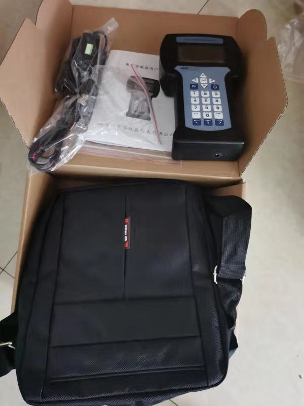
Coriolis mass flowmeters measure mass flow by detecting the dynamic behavior of vibrating measuring tubes.
HART-enabled instruments such as Micro Motion 1700 transmitters can provide valuable information about sensor performance and operating conditions.
Typical diagnostic parameters include:
- Mass flow and density.
- Sensor temperature.
- Drive gain.
- Pickoff amplitude.
- Tube frequency.
- Live zero.
- Active alarms.
9.1 Understanding Drive Gain
Drive gain indicates the drive effort required to maintain the sensor’s vibration.
An abnormal change may be associated with:
- Entrained gas.
- Two-phase flow.
- Excessive mechanical damping.
- Material coating.
- Sensor problems.
- Changing process conditions.
There is no single universal drive-gain percentage that defines normal operation for every Coriolis sensor.
Interpret the value against the specific model, fluid conditions, manufacturer guidance, and historical operating baseline.
9.2 Zero Verification vs. Zero Calibration
This distinction is extremely important.
Zero verification determines whether the existing zero reference remains suitable.
Zero calibration establishes a new zero reference.
A Coriolis flowmeter does not necessarily require field zero calibration every time it is installed or started.
In many cases, the factory zero is preferable.
Before considering a field zero:
- Verify the manufacturer’s recommended conditions.
- Allow the instrument and process temperature to stabilize.
- Ensure the sensor is completely filled with the appropriate fluid.
- Establish genuine zero-flow conditions.
- Review current diagnostics and zero stability.
- Perform zero verification where supported.
Only perform zero calibration when justified by the verification result, commissioning procedure, or manufacturer instructions.
Field warning: Never zero a Coriolis flowmeter while fluid is moving through the measuring tubes. An incorrect zero can introduce systematic measurement errors.
10. Sensor Trim, Range Configuration and Output Trim: What Is the Difference?
Three operations are frequently confused during field maintenance.
10.1 Range Configuration
Range configuration changes the relationship between the measured variable and the analog output.
For example, a pressure transmitter may be changed from a 0–10 bar output range to a 0–16 bar output range.
This is not sensor calibration.
10.2 Sensor Trim
Sensor trim adjusts the sensor measurement using an appropriate reference, following a model-specific calibration method.
It must be performed only when the required reference conditions and equipment are available.
10.3 Analog Output Trim
Analog output trim corrects the electrical current output relationship.
For example, the transmitter may command 12 mA while a suitable reference instrument measures a small deviation.
The correction concerns the output circuit, not the underlying pressure, temperature, level, or flow measurement.
Practical rule: If the digital process value is correct but the analog current is inaccurate, investigate the output circuit before adjusting the sensor.
11. Common HART Communication Problems
When a HART 475 cannot communicate with an instrument, follow a systematic troubleshooting sequence.
| Symptom | Possible Cause | Recommended Check |
|---|---|---|
| No device found | Incorrect connection or insufficient communication impedance | Inspect loop wiring and communication connection |
| Communication intermittent | Electrical interference or poor connections | Check terminals, shielding, grounding, and cable routing |
| Device detected but menus incomplete | Missing or incompatible DD | Verify device identity and DD support |
| Unexpected output current | Fault output, simulation, or incorrect scaling | Check diagnostics and output status |
| Multiple-device communication problems | Addressing or polling configuration | Verify HART addresses and multidrop configuration |
| Parameter cannot be changed | Write protection or access restriction | Check device security settings and operating state |
Check the Power Supply
A transmitter may operate incorrectly or lose communication when the terminal voltage falls below the manufacturer’s minimum requirement.
Remember that the voltage available at the transmitter depends on the power supply and the voltage drops across all series components.
Check Grounding and Shielding
Improper cable shielding, grounding, and routing can increase communication noise.
Follow the manufacturer’s instructions for cable termination and shielding arrangements. Do not assume that grounding both ends of every shield is appropriate for all installations.
Check Device Addressing
In conventional point-to-point installations, the transmitter commonly operates with polling address zero.
Multidrop installations may use different addresses and output behavior.
Always verify the selected operating mode and the receiving control system’s requirements.
12. Safety Precautions Before Changing HART Parameters
HART communicators provide convenient access to instrument settings, but configuration changes can affect live industrial processes.
Before modifying a device, confirm:
- The correct instrument and tag number.
- The process operating condition.
- The existing configuration and available backup.
- The effect of changes on analog output and digital variables.
- Relevant interlocks, alarms, and control functions.
- The required work authorization and change management procedure.
For safety instrumented systems, follow the approved site-specific maintenance and bypass procedures.
A parameter modification must never be made simply because the communicator allows it.
Special Warning: Loop Test and Simulation
Loop testing may force a transmitter to output a fixed current.
The receiving PLC or DCS may interpret that current as a real process measurement.
This can affect alarms, controllers, or interlocks.
Before performing a loop test, coordinate with operations and establish approved safeguards.
After testing, return the instrument to normal measurement mode and verify the actual output.
Likewise, make sure any simulation function is disabled before returning the instrument to service.
13. Practical HART Troubleshooting Checklist
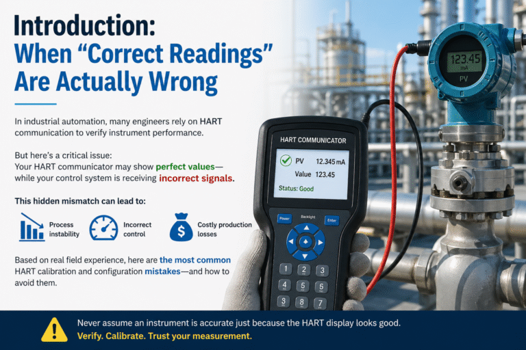
A reliable troubleshooting method should move from observation to verification rather than immediately changing parameters.
Step 1 — Identify the instrument
Confirm the manufacturer, model, tag number, firmware, and applicable documentation.
Step 2 — Check the process
Confirm that actual pressure, temperature, flow, or level conditions are understood.
Step 3 — Read the digital measurement
Compare the HART process variable with the local display, control-system indication, and independent reference where available.
Step 4 — Review diagnostics
Record all active alerts before resetting, acknowledging, or clearing them.
Step 5 — Inspect configuration
Check engineering units, output range, damping, sensor configuration, and application parameters.
Step 6 — Examine installation conditions
Look for wiring problems, blocked impulse lines, poor grounding, empty pipes, vibration, or radar reflections.
Step 7 — Perform authorized tests
Use loop testing, sensor verification, or calibration only when necessary and under approved conditions.
Step 8 — Restore normal operation
Disable simulations, confirm output behavior, verify alarm status, and document the maintenance results.
14. Final Thoughts: Diagnose First, Calibrate Only When Necessary

The HART 475 Field Communicator remains a useful maintenance tool for many installed smart instruments.
However, successful troubleshooting depends more on understanding the measurement principle and process conditions than on memorizing menu sequences.
Whether working with a Rosemount pressure transmitter, Yokogawa differential pressure instrument, Endress+Hauser radar level transmitter, or Micro Motion Coriolis flowmeter, the same engineering principles apply:
Identify the device, understand the process, review diagnostics, verify the signal chain, and avoid unnecessary adjustments.
A configuration change should solve an identified problem—not introduce a new one.
At Zero Instrument, we support industrial flow, level, pressure, and temperature measurement applications across different industries. Correct instrument selection, reliable installation, and systematic troubleshooting are essential to achieving stable measurement performance.
For assistance with instrument selection, measurement applications, or technical specifications, visit www.zeroinstrument.com.
Technical Disclaimer: This article is intended as general engineering guidance. The examples are not verified device-specific HART menu maps or complete manufacturer diagnostic-code lists. Always consult the correct device manual, firmware documentation, and applicable site procedures before modifying, testing, or calibrating industrial instruments.