Flow meters are the backbone of modern industrial automation and process control. Whether in chemical production, water treatment, or oil and gas transmission, precise flow measurement ensures safety, product quality, and cost efficiency.
However, even the most advanced flow meters drift over time due to wear, temperature stress, and process conditions.
Establishing proper calibration intervals is therefore essential — not just for accuracy, but also for compliance with metrological and safety standards.
This guide provides a comprehensive overview of calibration intervals and key practices for five major types of flow meters: differential pressure, ultrasonic, electromagnetic, turbine, and vortex.
It also explains how to adjust calibration cycles according to working conditions, industry requirements, and failure history.

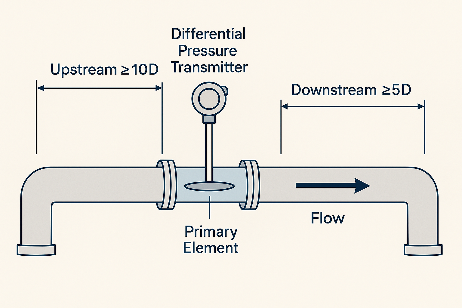
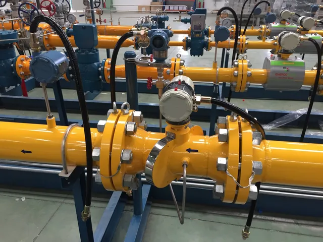
1. Differential Pressure Flow Meters
(Including Orifice Plate, Venturi, and V-Cone Types)
Recommended Calibration Intervals
Standard conditions (clean medium, stable pressure and temperature, e.g. water or air): every 12–24 months.
Harsh conditions (containing solids, corrosive media, or high temperature/pressure steam): every 6–12 months.
Critical applications (trade measurement, safety interlock systems): every 6 months per national metrology regulations.
Calibration Focus
Verify differential pressure–flow linearity, zero drift, and span accuracy.
The total error must comply with the accuracy grade (e.g., ±1.0% for Class 1.0 meters).
Calibration Methods
On-site verification – Compare with a certified standard orifice or portable ultrasonic flow meter under identical conditions.
Laboratory calibration – Test the differential pressure transmitter using a standard pressure source (e.g., piston gauge). Inspect the orifice edge for wear or scaling; if edge wear exceeds 0.1 mm, replace it before recalibration.
Practical Tips
Always isolate the meter, drain the process fluid, and clean the orifice plate before calibration. Any residue or corrosion on the edge can distort the differential pressure reading.
2. Ultrasonic Flow Meters
(Clamp-on, Insertion, and Inline Types)
Recommended Calibration Intervals
Clamp-on (non-contact type): every 12–18 months (no wear, but coupling gel may age).
Insertion/inline type:
Clean liquids: 12–24 months
Slurries or viscous media: 8–12 months
Calibration Focus
Check sound-path travel time, velocity calculation accuracy, and zero stability.
For inline meters, also verify pipe diameter compatibility and transducer alignment.
Calibration Methods
Field calibration – Use bucket (volumetric) method or reference meter method (series connection with a verified electromagnetic or turbine meter). Ensure proper re-application of coupling gel and probe contact.
Laboratory calibration – Connect the inline meter to a gravimetric or bell-prover standard at various flow rates; check the impact of probe position on measured velocity.
Practical Tips
Remove air bubbles before testing, as they reflect ultrasound and cause signal distortion. Clean any rust or paint on the pipe surface to improve transmission efficiency.
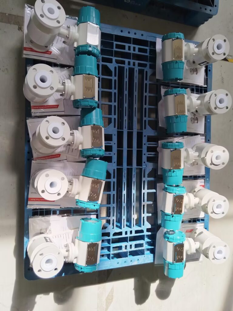
3. Electromagnetic Flow Meters
Recommended Calibration Intervals
Normal service (clean conductive fluids): every 18–24 months.
Severe service (slurry, pulp, corrosive chemicals): every 12 months.
Trade or safety measurement: every 6–12 months, as required by law.
Calibration Focus
Inspect electrode insulation resistance, excitation current stability, and flow accuracy (typical tolerance: ±0.5–1.0%).
Calibration Methods
On-site method – Use a reference flow meter in series at multiple points (20%, 50%, 80% of range).
Laboratory method – Remove the sensor, connect to a flow standard rig, and verify electrode and liner integrity.
Zero-point test – Close upstream/downstream valves, ensure full pipe but zero flow, and confirm reading returns to zero.
Practical Tips
Before calibration, cut off power and confirm proper grounding (≤4 Ω). For coated electrodes, gently clean with a soft cloth — never use sharp tools that can damage PTFE or rubber liners.
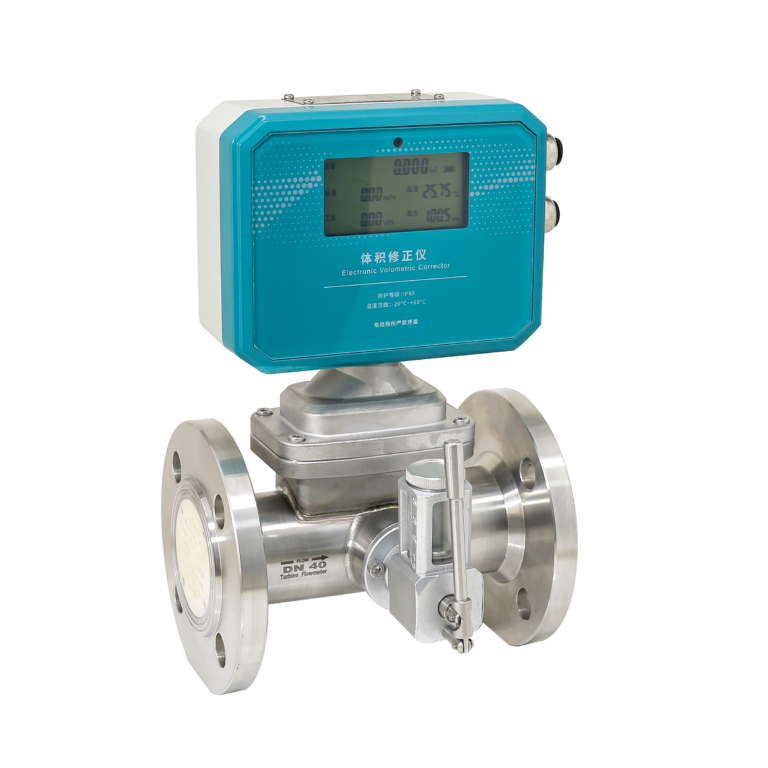
4. Turbine Flow Meters
Recommended Calibration Intervals
Clean, low-viscosity liquids or gases: every 12 months.
Viscous or slightly contaminated fluids: every 6–8 months.
Gas service: every 12 months (requires extra verification of pressure and temperature compensation).
Calibration Focus
Validate linear relationship between turbine speed and flow, bearing friction, and pressure loss.
For high-accuracy models, total error should remain within ±0.2–0.5%.
Calibration Methods
Laboratory calibration – Connect to a liquid or gas flow standard (e.g., volumetric pipe standard or sonic nozzle system). Recalculate the K-factor (pulses per unit flow); if deviation exceeds ±0.3%, reprogram the transmitter.
Field inspection – Rotate the impeller manually to ensure no sticking or abnormal noise. Replace worn bearings before calibration.
Practical Tips
After reinstallation, maintain straight-pipe sections (upstream ≥10D, downstream ≥5D). For gas turbines, verify the accuracy of the temperature and pressure compensation modules using standard gauges.
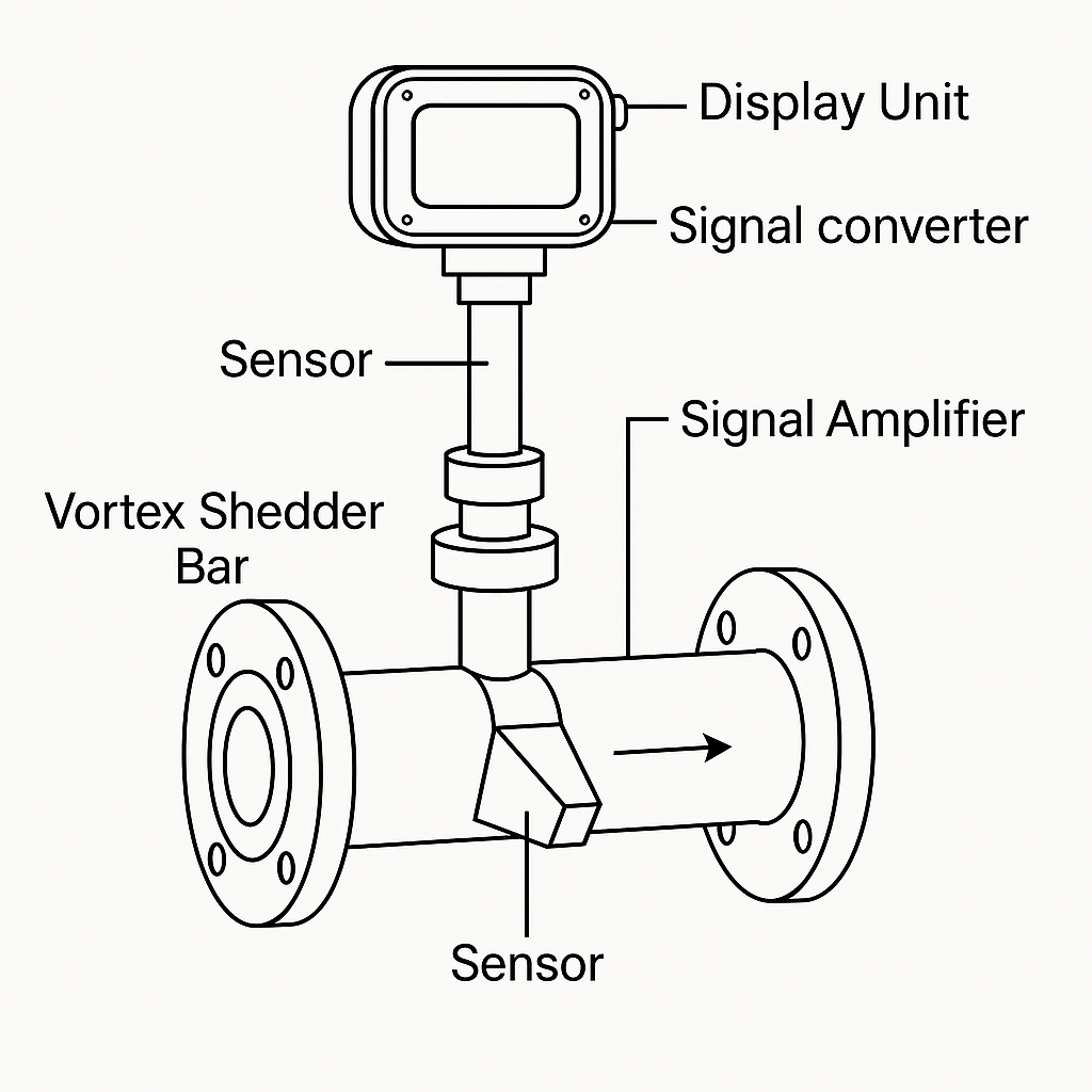
5. Vortex Flow Meters
Recommended Calibration Intervals
Gas or steam service: every 18–24 months.
Liquid service: every 12–18 months.
High-temperature service (>300 °C): every 12 months due to sensor aging.
Calibration Focus
Verify vortex frequency-to-flow correspondence, amplifier sensitivity, and zero stability (tolerance ±0.5–1.0%).
Calibration Methods
On-site verification – Compare with a reference vortex or electromagnetic meter at 30–100% of the range. For steam, record pressure and temperature simultaneously and convert to standard conditions.
Laboratory calibration – Simulate actual flow and verify signal-processing accuracy. Replace damaged piezoelectric sensors before recalibration.
Practical Tips
Clean any scale or residue on the bluff body with a soft brush. Avoid damaging its sharp edges — erosion alters vortex formation and increases measurement error.
6. Adjusting Calibration Intervals
Even with fixed schedules, calibration frequency must adapt dynamically to operating performance. Three key adjustment principles apply:
(1) Fault-Based Adjustment
If a meter shows two or more deviations (e.g., unstable readings or zero drift) within one cycle, shorten the next calibration interval by 50% (e.g., from 12 months to 6 months).
If two consecutive calibrations are passed, restore the original interval.
(2) Process or Medium Change
When the process medium or conditions change — for example, from clean water to slurry, or pressure from 0.5 MPa to 2.0 MPa — perform an immediate recalibration and shorten the next cycle by 30–50%.
(3) Industry Standards Priority
Chemical industry: comply with GB 50093-2013, where safety-critical meters must be verified every ≤12 months.
Energy/natural gas sector: follow JJG 1037-2008 requiring bi-annual verification for custody-transfer applications.
7. Recordkeeping and Continuous Improvement
Each calibration event should be recorded with:
Date and technician name
Method and reference standard
Error before/after adjustment
Maintenance or part replacement notes
By maintaining a digital calibration database, users can track drift trends, optimize intervals, and forecast potential failures before they affect process integrity.

Conclusion
A well-planned calibration schedule is not just routine maintenance — it is a strategic control process that guarantees accuracy, compliance, and reliability across an entire plant.
By aligning calibration intervals with instrument type, process conditions, and regulatory standards, operators can significantly extend instrument lifespan and minimize unplanned downtime.