
A Practical Guide to Flameproof, Increased Safety, and Intrinsic Safety Equipment Selection
In hazardous industrial environments, selecting the correct explosion protection method is essential for personnel safety, equipment reliability, and regulatory compliance.
One common mistake during instrument selection is assuming that a higher explosion protection rating is always better.
However, Ex d, Ex e, and Ex i do not represent different levels of the same protection method. They are three fundamentally different approaches to preventing ignition in hazardous areas.
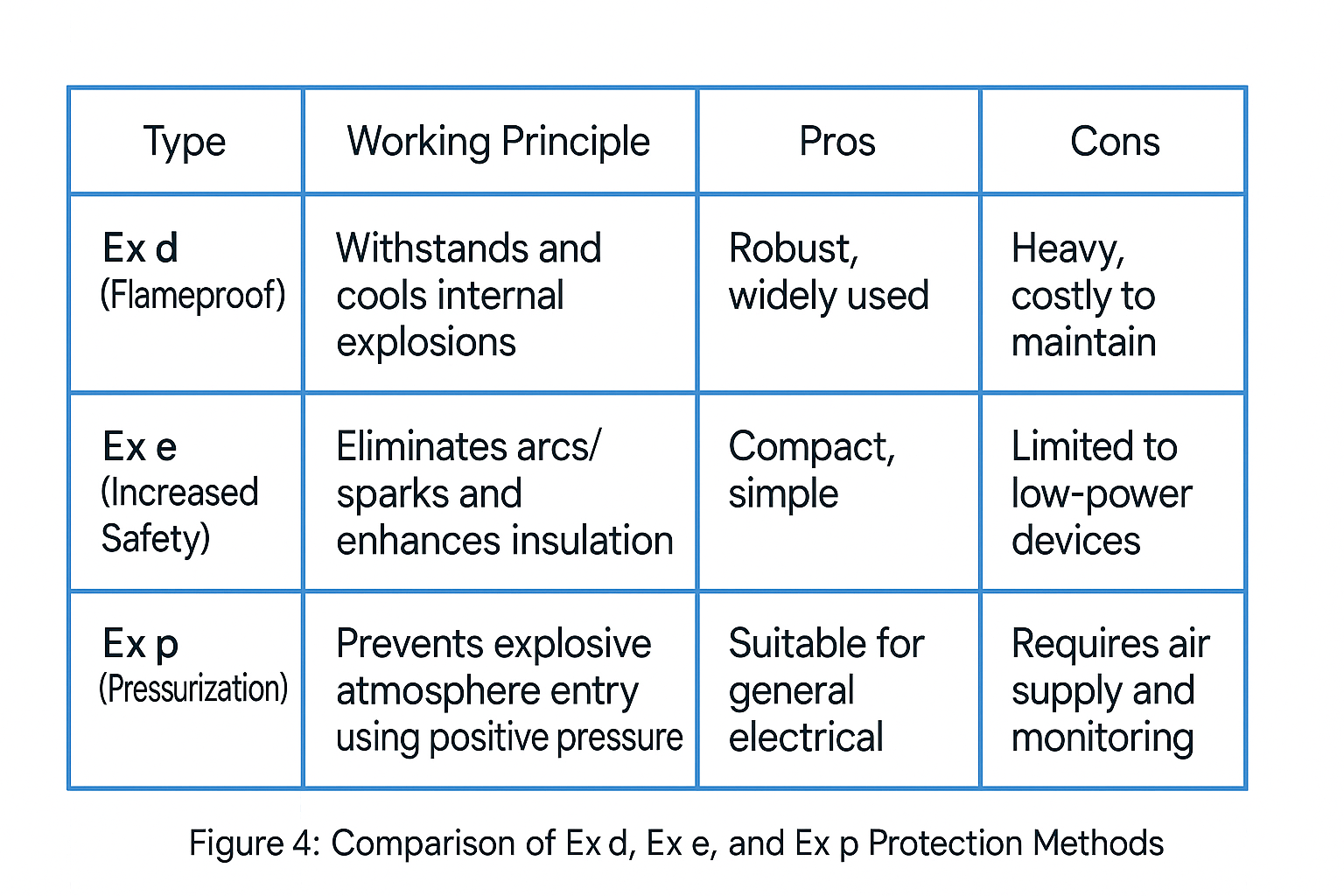
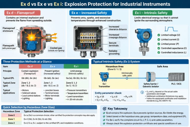
- Ex d (Flameproof): Contains an internal explosion and prevents the flame from spreading outside the enclosure.
- Ex e (Increased Safety): Prevents arcs, sparks, and excessive temperatures through enhanced electrical and mechanical construction.
- Ex i (Intrinsic Safety): Limits electrical energy so that it cannot ignite the surrounding explosive atmosphere under specified conditions.
In simple terms:
Ex d contains the explosion. Ex e prevents ignition sources from occurring. Ex i limits the energy so ignition cannot occur.
Understanding these differences will help engineers select the right instruments for their actual operating conditions.
1. Understanding the Three Explosion Protection Methods
1.1 Ex d – Flameproof Protection
Working Principle
Ex d equipment uses a strong enclosure designed to withstand an internal explosion.
If an explosive gas mixture inside the enclosure ignites, the enclosure contains the resulting pressure. Hot gases escaping through the carefully engineered flameproof joints are cooled sufficiently to prevent ignition of the surrounding atmosphere.
This allows certain electrical components that may generate arcs or sparks during normal operation to be installed inside the enclosure.
Typical Applications
- Electric motors
- Explosion-proof solenoid valves
- Local control stations
- Explosion-proof junction boxes
- Industrial lighting
- Some local display instruments
Hazardous Area Classification
- Ex db (EPL Gb): Generally suitable for Zone 1 and Zone 2.
- Ex dc (EPL Gc): Generally suitable for Zone 2.
The actual permitted application must always be confirmed against the equipment certificate.
Important Installation Requirements
The flameproof enclosure is only effective when its certified construction remains intact.
Pay particular attention to:
- Flameproof joint surfaces
- Cable glands and cable entries
- Enclosure bolts and fasteners
- Unused cable entry openings and certified stopping plugs
Never open flameproof equipment while energized unless the equipment certification and applicable procedures explicitly permit it.
Damaged flamepaths, corrosion, incorrect cable glands, or ordinary replacement plugs can compromise explosion protection.
1.2 Ex e – Increased Safety Protection
Working Principle
Ex e equipment is designed so that arcs, sparks, and dangerous temperatures are not expected to occur during normal operation.
Additional safety measures are applied to reduce the possibility of ignition, including:
- Improved insulation
- Increased electrical clearance distances
- Increased creepage distances
- Temperature control
- Secure electrical connections
- Improved mechanical construction
Unlike Ex d, Ex e does not rely on a flameproof enclosure to contain an internal explosion.
The equipment must be designed to prevent ignition sources within the limits of its certified protection concept.
Typical Applications
- Junction boxes
- Terminal boxes
- Motor terminal compartments
- Increased-safety lighting
- Certain electrical equipment and components
Understanding Ex eb and Ex ec
These two markings should not be treated as interchangeable.
- Ex eb (EPL Gb): Generally suitable for Zone 1 and Zone 2.
- Ex ec (EPL Gc): Generally suitable for Zone 2.
Their construction requirements and permitted internal components differ.
Always check the certified protection level and equipment documentation before installation.
Important Installation Requirements
Ex e equipment depends heavily on correct installation and maintenance.
Loose terminals, poor electrical connections, overload conditions, and inappropriate replacement components can compromise safety.
Do not assume that an ordinary switch, relay, or other arc-producing component can be installed inside an Ex e enclosure without additional certified protection.
1.3 Ex i – Intrinsic Safety Protection
Working Principle
Intrinsic safety takes a different approach.
Instead of containing an explosion or relying primarily on improved enclosure construction, Ex i limits the electrical energy available in the circuit.
Voltage, current, power, capacitance, and inductance are controlled so that electrical sparks or thermal effects cannot ignite the surrounding atmosphere under the specified normal and fault conditions.
This protection method is particularly suitable for low-power instrumentation and signal circuits.
Protection Levels
- Ex ia (EPL Ga): Commonly used for Zone 0, Zone 1, and Zone 2 applications.
- Ex ib (EPL Gb): Generally used for Zone 1 and Zone 2.
- Ex ic (EPL Gc): Generally used for Zone 2.
Ex ia is widely used for instruments installed in Zone 0, but it is not the only possible protection concept that can achieve EPL Ga. The complete equipment marking and certification must be checked.
Typical Applications
- Pressure transmitters
- Differential pressure transmitters
- Temperature transmitters
- Level transmitters
- Gas detectors
- RTDs and thermocouples
- 4-20 mA instrumentation circuits
A Critical Point: Intrinsic Safety Applies to the Complete Circuit
An intrinsically safe instrument cannot be considered independently of its associated circuit.
A typical system includes:
- Field instrument
- Intrinsically safe cable
- Safety barrier or galvanic isolator
- Control system or PLC/DCS
The electrical parameters of these components must be compatible.
The safety barrier limits the energy that can reach the hazardous-area instrument. Incorrect combinations can invalidate the intrinsic safety design.
Maintenance Considerations
Intrinsic safety can simplify certain inspection and maintenance activities.
However, energized work, disconnection, and replacement must still follow the equipment certification, approved system documentation, and applicable site procedures.
Adding equipment, changing cables, or extending cable lengths without checking the circuit parameters can compromise intrinsic safety.
2. How to Select the Correct Explosion Protection Method
A reliable selection process should follow the actual hazardous-area conditions rather than starting with the instrument price or protection marking.
Step 1: Identify the Hazardous Area
First, determine where the instrument will be installed.
For gas atmospheres:
- Zone 0: Explosive gas atmosphere is present continuously, frequently, or for long periods.
- Zone 1: Explosive gas atmosphere is likely to occur occasionally during normal operation.
- Zone 2: Explosive gas atmosphere is not likely to occur during normal operation, and if it does occur, it will exist only for a short time.
For combustible dust atmospheres:
- Zone 20
- Zone 21
- Zone 22
Dust hazardous areas require appropriate dust protection, such as Ex t equipment with the relevant Group III classification.
Gas-certified equipment should not automatically be considered suitable for dusty environments.
Step 2: Identify the Gas Group and Temperature Class
For gas applications, equipment must be suitable for the specific gas or vapor present.
The main gas groups are:
- IIA
- IIB
- IIC
IIC equipment generally provides a higher level of protection against gas ignition characteristics and can often be used in IIB and IIA environments, provided all other certification conditions are satisfied.
However, IIA or IIB equipment must not automatically be used in an IIC environment.
Next, check the temperature class.
| Temperature Class | Maximum Equipment Surface Temperature |
|---|---|
| T1 | 450°C |
| T2 | 300°C |
| T3 | 200°C |
| T4 | 135°C |
| T5 | 100°C |
| T6 | 85°C |
The maximum permitted equipment surface temperature must remain below the ignition temperature of the surrounding gas or vapor.
Remember that ignition can be caused by excessive surface temperature even when no electrical spark occurs.
Step 3: Consider the Equipment’s Electrical Characteristics
Now consider the instrument itself.
A practical selection guide is:
| Equipment Characteristics | Common Protection Choice |
|---|---|
| High-power equipment or equipment that may generate arcs and sparks | Ex d |
| Static electrical connections and components designed not to produce ignition sources | Ex e |
| Low-power measurement and signal circuits | Ex i |
This is a practical starting point, not a substitute for equipment certification.
Some instruments use combined protection concepts, such as Ex de, where different parts of the equipment use different protection methods.
Step 4: Verify Intrinsic Safety Circuit Parameters
If Ex i is selected, the field instrument and associated apparatus must satisfy the applicable entity parameter requirements.
The field instrument provides the following parameters:
- Ui: Maximum input voltage
- Ii: Maximum input current
- Pi: Maximum input power
- Ci: Internal capacitance
- Li: Internal inductance
The safety barrier provides:
- Uo: Maximum output voltage
- Io: Maximum output current
- Po: Maximum output power
- Co: Maximum permitted external capacitance
- Lo: Maximum permitted external inductance
The basic entity parameter checks are:
Uo <= Ui
Io <= Ii
Po <= Pi

Ci + Cc <= Co
Li + Lc <= Lo
Where:
- Cc = Total cable capacitance
- Lc = Total cable inductance
All five conditions must be checked.
Cable capacitance and inductance increase with cable length. Therefore, the maximum permitted cable length must be calculated using the actual cable parameters and the certified equipment data.
Special attention is required for IIC circuits, where allowable capacitance and inductance can be particularly restrictive.
Important: These basic equations are an initial entity parameter check. They are not sufficient for every intrinsically safe system.
When capacitance and inductance are both significant, additional restrictions or combined parameter limitations may apply. Always follow the equipment certificates, control drawings, and applicable installation standards.
Cable shielding, separation from non-intrinsically safe circuits, and grounding arrangements must also follow the approved system design and manufacturer’s instructions.
Step 5: Check the Complete Explosion Protection Certificate
Never select equipment based only on the presence of an Ex marking.
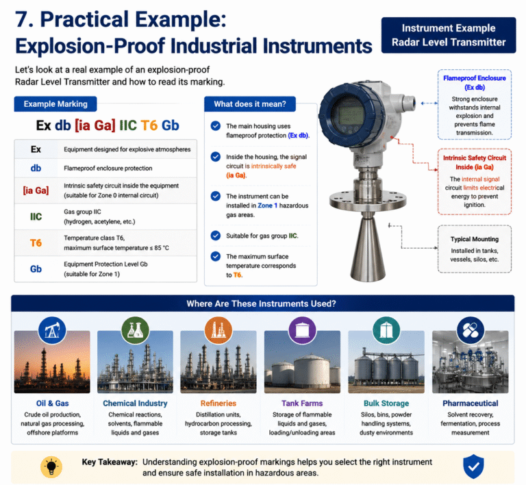
A typical gas explosion protection marking may look like:
Ex db IIC T4 GbAnother example is:
Ex ia IIC T4 GaEach part provides important information:
- Ex: Explosion protection marking
- d / ia: Protection method
- IIC: Gas group
- T4: Temperature class
- Gb / Ga: Equipment Protection Level (EPL)
Check the following before approving the equipment:
- Hazardous area classification
- Gas or dust group
- Temperature class
- Equipment Protection Level
- Ambient temperature range
- Process temperature and other operating limitations
- Certified cable glands and installation accessories
- Special conditions of use stated in the certificate
For combined protection, such as Ex de, check the complete certificate to understand which parts use each protection method and the permitted installation conditions.
For example, Ex de typically combines a flameproof enclosure with an increased-safety terminal compartment.
The certified protection level of the complete equipment determines its permitted application.
3. Quick Reference: Hazardous Zones and Protection Methods
The following is a practical reference for common gas hazardous-area applications.
| Hazardous Area | Typical Protection Selection |
|---|---|
| Zone 0 | Ex ia (Ga) is a common choice; other certified Ga protection concepts may also apply |
| Zone 1 | Ex d (Gb), Ex ib (Gb), Ex eb (Gb) |
| Zone 2 | Ex d, Ex e, Ex i, subject to the certified EPL and installation conditions |
For dust hazardous areas, select equipment specifically certified for the relevant Zone 20, 21, or 22 application and Group III dust classification.
Always verify the complete equipment marking rather than relying on this simplified reference table.
4. Four Common Mistakes in Explosion-Proof Instrument Selection
Mistake 1: Assuming Ex d Is Always the Highest Protection Level
Ex d is a flameproof protection method, not a universal ranking of explosion protection.
For example, an Ex db instrument with EPL Gb is generally not suitable for Zone 0.
Zone 0 requires equipment with EPL Ga.
Mistake 2: Connecting an Intrinsically Safe Instrument Directly to an Ordinary Power Supply
An Ex ia instrument does not automatically make the entire circuit intrinsically safe.
The associated apparatus, cable parameters, and circuit design must all meet the applicable requirements.
Using an incorrect safety barrier or bypassing the energy-limiting arrangement can invalidate the protection.
Mistake 3: Checking Only Whether the Equipment Has an Ex Marking
A marking such as Ex alone does not provide enough information for equipment selection.
Gas group, temperature class, protection method, EPL, and certificate conditions must all be checked.
Also remember that gas explosion protection and dust explosion protection are different certification systems.
Mistake 4: Using Ex e Equipment for Unsuitable Electrical Components
Ex e is intended for equipment constructed to prevent ignition sources under its specified operating conditions.
Installing unsuitable switches, contacts, or other arc-producing components can compromise the protection concept.
Similarly, Ex eb and Ex ec have different requirements and permitted applications.
5. Final Selection Checklist
Before purchasing or installing an explosion-protected instrument, confirm the following:
-
Hazardous area zone has been identified.
-
Gas or dust classification has been confirmed.
-
Equipment gas group or dust group is suitable.
-
Temperature class is appropriate.
-
Equipment Protection Level meets the area requirements.
-
Protection method matches the instrument design.
-
Intrinsic safety circuit parameters have been verified, where applicable.
-
Cable glands and accessories are appropriately certified.
-
Installation and maintenance requirements have been reviewed.
-
Explosion protection certificates have been checked.
Conclusion
Ex d, Ex e, and Ex i are not competing protection levels. They are different engineering solutions designed for different equipment structures and operating conditions.
The correct selection depends on the hazardous area, the surrounding atmosphere, the electrical characteristics of the instrument, and the applicable certification requirements.
A practical selection sequence is:
Identify the zone → Determine the gas or dust group → Check the temperature class → Select the protection method → Verify circuit parameters → Confirm the certificate.
There is no universally best explosion protection method. There is only the protection method that is suitable for the specific application.
In hazardous industrial environments, never rely on assumptions or appearance alone. Always follow the hazardous-area classification documents, approved engineering design, applicable standards, and certified equipment documentation.
Correct selection is the foundation of safe and reliable instrumentation.