Pulse (Frequency) Output Wiring
Frequency and Pulse output is operated through the same terminal POUT (P+) & PCOM
(P-). Customers can select one of them by the parameter setting menu. Frequency/Pulse
output support three models as below;
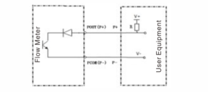
Output Model 1: OC gate is passive output, user need to connect a pull-up resistor
The ON/OFF switch of the remote transmitter (red switch in wiring cavity) needs to dial inward(off position).
The ON/OFF switch of the compact transmitter needs to dial down or left (off
position).
POUT (P+) Output frequency/pulse signal
External power V+ can support 5V/12V/24V, resistance range of pull-up resistor is 2k-10k
Output Model 2: OC gate is passive output, user need to connect the pull-down resistor.
The ON/OFF switch of the remote transmitter (red switch in wiring cavity) need to dial inward (off position).
The ON/OFF switch of the compact transmitter needs to dial down or left (off position).
POUT (P-) Output frequency/pulse signal.
POUT (P+) Connect external power V+
This model is widely used in an integrated system between flow meter and PLC.
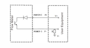
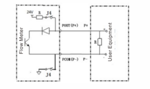
Output Model 3: Level mode active output that directly drives the load.
The two-way dial switch (red dial switch in the wiring cavity) of the split converter
is turned outward (ON position), and the two-position dial switch of the integrated
a terminal board is dialed or turned to the right ( ON position)
2. Current output wiring
The current output is designed with a high-precision large-scale integrated circuit
chip.
It does not need zero and full-scale calibration.
The output is stable and reliable,
with good interoperability and temperature stability.
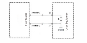
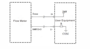
The current output has three terminals IOUT(I+), ICOM(|-), and Ivee, which
support two current output modes, two-wire power supply, and no power supply
current output.
Output Model 1: Two-wire current output
Terminals are IOUT(+) and ICOM(1-).
Output Model 2: Two-wire passive current output
Terminals are IOUT(I+) and ICOM(1-).

