
Your pump is running. The valve is open. There is liquid in the pipeline.
But the electromagnetic flow meter still reads zero.
What should you check first?
Some technicians immediately check the grounding connection. Others disable the empty-pipe detection function or suspect that the transmitter has failed.
However, a running process does not necessarily mean that the flow meter has the conditions required for a valid measurement.
A zero reading can be caused by process conditions, a partially filled pipe, insufficient conductivity, electrode problems, grounding or potential-equalization issues, transmitter settings, signal wiring, or the DCS input channel.
The key is to troubleshoot the problem in the correct order.
1. Is the Local Flow Meter Reading Zero, or Only the DCS?
Before touching the sensor, first determine where the zero reading actually occurs.
A reported “no flow” condition may mean several different things:
- The local instantaneous flow display is zero.
- The totalizer is not increasing.
- The 4–20 mA or pulse output indicates zero flow.
- The local display shows normal flow, but the DCS shows zero.
These symptoms should not be treated as the same problem.
If the local display shows a normal flow rate but the DCS shows zero, the sensor itself is probably not the first place to investigate.
Instead, check:
- Output configuration
- Actual 4–20 mA loop current
- Pulse or frequency output settings
- Signal isolators
- Wiring
- DCS analog input channel
- Engineering-unit scaling
- Lower and upper range settings
If both the local display and output signal are zero, move your investigation toward the process conditions, sensor, electrodes, transmitter parameters, and internal electronics.
Quick Troubleshooting Table
| Symptom | What to Check First |
|---|---|
| Local display = 0, DCS = 0 | Actual flow, full-pipe condition, conductivity, low-flow cutoff |
| Local display normal, DCS = 0 | 4–20 mA output, wiring, isolator, I/O channel, DCS scaling |
| Empty-pipe alarm | Full-pipe condition, electrode contact, conductivity, detection settings |
| Reading occasionally drops to zero | Air bubbles, partial filling, low flow, electrode coating |
| Reading is unstable | Grounding/potential equalization, bubbles, electrical noise, electrode condition |
This first distinction can save a significant amount of troubleshooting time.
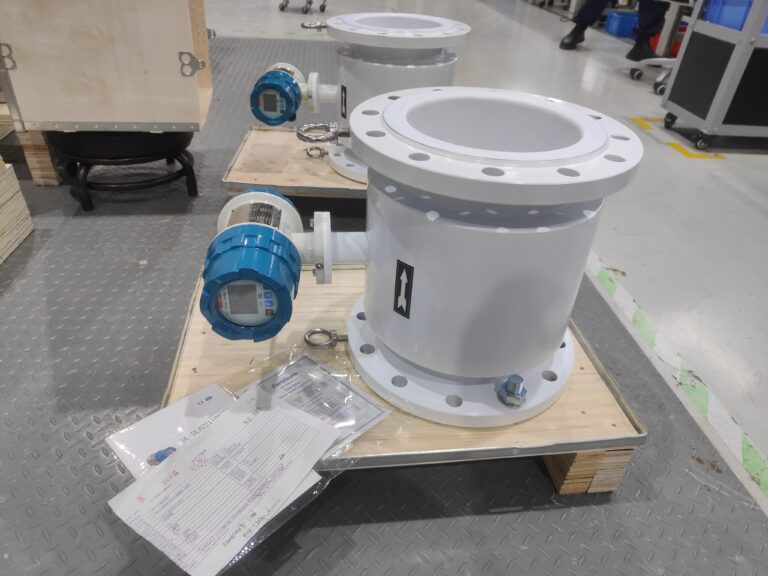
2. Three Basic Conditions Required for Electromagnetic Flow Measurement
An electromagnetic flow meter measures flow according to Faraday’s law of electromagnetic induction.
When a conductive liquid moves through the magnetic field generated by the sensor, a voltage is induced across the measuring electrodes. This voltage is related to the average velocity of the liquid.
For a conventional full-bore electromagnetic flow meter to operate correctly, three basic conditions generally need to be satisfied:
1. The liquid must be sufficiently conductive
Electromagnetic flow meters cannot measure non-conductive fluids in the same way they measure conductive liquids.
The minimum required conductivity depends on the particular flow meter, sensor design, and application.
Therefore, do not assume that one conductivity limit applies to every magnetic flow meter. Always check the manufacturer’s specifications for the exact model.
2. The measuring tube should be completely filled
Having liquid somewhere inside the pipeline is not the same as having a completely filled measuring tube.
A partially filled pipe can change electrode contact conditions and disturb the velocity profile, making the measurement unreliable.
3. The conductive liquid must actually be moving
Pipeline pressure does not mean flow.
A pipe can be completely filled and pressurized while the liquid velocity is zero. In that situation, a correctly operating electromagnetic flow meter should indicate approximately zero flow.
This is why:
Pump running + valve open ≠ guaranteed measurable flow through the flow meter.
3. Full Pipe Does Not Simply Mean “There Is Liquid in the Pipeline”
One of the most common troubleshooting mistakes is assuming that the flow meter must be full because liquid exists in the pipeline.
Problematic installation locations may include:
- High points in horizontal pipelines
- Free-discharge lines
- Locations without sufficient downstream backpressure
- Pump suction areas where air may be introduced
- Pipelines where gas can accumulate
- Low-flow applications with gas-liquid separation
For example, a downstream pipe may contain liquid while the upper part of the flow meter measuring tube contains air.
The meter is therefore not operating under a true full-pipe condition.
Vertical Installation
For vertical piping, upward flow is generally preferable because it helps maintain a completely filled measuring tube and reduces the possibility of gas accumulation.
Horizontal Installation
For horizontal installations, electrode orientation and transmitter position should follow the requirements of the specific manufacturer and sensor design.
Correct orientation can help prevent gas accumulation around the electrodes and reduce sediment-related measurement problems.
Some electromagnetic flow meters also have dedicated empty-pipe detection electrodes whose effectiveness depends on sensor orientation.
Therefore, installation rules should always be verified against the manual for the exact instrument.
How to Verify a Full-Pipe Condition
Do not rely only on the P&ID or pipeline drawing.
Consider:
- Upstream and downstream elevations
- Pump condition
- Valve positions
- Bypass lines
- Pipeline pressure
- Discharge configuration
- Actual flow direction
- Possible air pockets
- Process operating conditions
When necessary, confirm the actual hydraulic conditions together with process operators.
4. Check the Low-Flow Cutoff Setting
This is an easily overlooked cause of a zero reading.
Many electromagnetic flow transmitters include a low-flow cutoff function.
When the measured flow falls below the configured threshold, the transmitter may intentionally force the indicated flow to zero to prevent noise, drift, or very small fluctuations from being counted as actual process flow.
This creates a situation where:
Liquid is actually moving through the pipe, but the transmitter displays 0.00.
If the process is operating at a very low flow rate, check:
- Actual expected flow rate
- Flow meter measuring range
- Low-flow cutoff value
- Zero suppression settings
- Current output behavior near zero
Do not simply disable the function without understanding why it was configured.
Instead, determine whether the cutoff value is appropriate for the application.
5. A Tight Ground Wire Does Not Necessarily Mean Correct Potential Equalization
Electromagnetic flow meters measure very small electrode signals.
For stable measurement, the liquid and sensor need a reliable electrical reference according to the instrument manufacturer’s design.
A common field mistake is to treat protective grounding, instrument grounding, and process-medium potential equalization as exactly the same thing.
They are not necessarily interchangeable.
The correct arrangement depends on factors such as:
- Pipeline material
- Pipe lining
- Flange construction
- Sensor design
- Presence of reference electrodes
- Manufacturer requirements
Conductive metal piping, internally lined piping, and plastic piping may require different arrangements.
Some installations require grounding rings or grounding electrodes. Others may not require additional grounding rings at all.
Therefore:
A grounding ring is not a universal solution for every electromagnetic flow meter problem.
When investigating a suspected grounding issue, check:
- Manufacturer wiring diagram
- Exact sensor model
- Grounding/potential-equalization connection points
- Loose or corroded connections
- Paint or coatings at required electrical contact points
- Signal cable routing
- Excitation cable routing on remote-type meters
- Separation from power cables
Avoid temporary or improvised grounding connections unless they are specifically permitted by the manufacturer.
6. An Empty-Pipe Alarm Does Not Always Mean the Pipe Is Completely Empty
Many electromagnetic flow meters provide empty-pipe detection.
Depending on the instrument design, this function may use the measuring electrodes or a dedicated detection electrode to determine whether adequate contact exists between the liquid and the electrodes.
When an empty-pipe alarm appears, the first step should still be:
Confirm whether the measuring tube is actually full.
If the pipe is definitely full, investigate other possible causes, including:
- Electrode coating
- Poor electrode contact with the liquid
- Changes in liquid conductivity
- Air bubbles
- Sensor orientation
- Empty-pipe detection threshold
- Wiring
- Commissioning parameters
A particularly important point is:
Disabling empty-pipe detection may remove the alarm without solving the measurement problem.
If poor electrode contact or an incorrect hydraulic condition is causing the alarm, switching off the diagnostic function can simply hide the symptom.
Empty-pipe detection methods, conductivity requirements, thresholds, menu names, and alarm behavior vary between manufacturers and models.
Always refer to the manual for the specific instrument.
7. Could Air Bubbles Cause a Zero or Unstable Reading?
Yes.
Entrained gas can affect electromagnetic flow measurement, particularly when gas accumulates near the electrodes or prevents the measuring tube from remaining completely full.
Potential sources include:
- Pump suction problems
- Cavitation
- Air entering through upstream piping
- Process degassing
- Poor installation location
- Horizontal pipe high points
- Intermittent low-flow operation
Depending on the amount and distribution of gas, the flow meter may show:
- Unstable readings
- Intermittent zero flow
- Empty-pipe alarms
- Signal diagnostic alarms
- Measurement errors
If the problem occurs only under certain operating conditions, compare the flow meter behavior with pump operation, pressure, valve position, and process changes.
8. What If the Local Display Is Correct but the DCS Shows Zero?
This is a different troubleshooting path.
If the transmitter itself displays a reasonable and stable flow rate, do not immediately remove the sensor or change its grounding arrangement.
Measure the actual output signal.
For a 4–20 mA system, determine whether the transmitter is actually producing the expected current.
Then check the complete signal chain:
Flow Meter → Wiring → Isolator/Barrier → DCS Analog Input → Scaling → Display
Possible problems include:
- Incorrect output assignment
- Wrong active/passive current-loop configuration
- Open circuit
- Incorrect polarity
- Signal isolator failure
- Wrong DCS input type
- Incorrect 4–20 mA scaling
- Wrong engineering units
- Incorrect configured flow range
For pulse, frequency, or RS485/Modbus communication, troubleshoot the corresponding output and receiving channel rather than treating the problem as a sensor failure.

9. A Practical Troubleshooting Sequence
When an electromagnetic flow meter shows zero despite apparent process flow, use the following sequence.
Step 1 — Check the Local Display
Record:
- Instantaneous flow
- Totalized flow
- Diagnostic messages
- Alarm codes
Determine whether the reading is continuously zero, intermittently zero, or unstable.
Step 2 — Compare the Local Meter with the DCS
If the local display is normal but the DCS reads zero, investigate the output loop and DCS before touching the sensor.
Step 3 — Confirm Actual Process Flow
Verify:
- Pump operation
- Valve position
- Bypass status
- Check valve condition
- Actual flow direction
- Process pressure
- Expected flow rate
Do not assume that a running pump automatically means liquid is flowing through the meter.
Step 4 — Confirm the Measuring Tube Is Full
Check installation elevation, downstream conditions, air accumulation, free discharge, and possible partial filling.
Step 5 — Check Basic Parameters
Review:
- Pipe diameter
- Flow direction
- Measuring range
- Low-flow cutoff
- Zero settings
- Output configuration
Step 6 — Check Diagnostic Alarms
If there is an empty-pipe alarm, investigate the full-pipe condition, electrodes, conductivity, orientation, and detection settings.
Step 7 — Check Grounding and Potential Equalization
Verify the installation according to the manufacturer’s wiring instructions rather than relying only on the presence of a ground wire.
Step 8 — Inspect the Sensor and Cables
After external causes have been eliminated, investigate:
- Electrode contamination
- Electrode condition
- Signal cable
- Excitation cable
- Moisture ingress
- Terminal connections
Step 9 — Investigate the Transmitter and Excitation Circuit
Only after the process conditions, installation, parameters, wiring, and sensor have been checked should internal transmitter or excitation-circuit problems become the primary suspect.
10. Troubleshooting Flowchart
A useful field logic is:
Does the local display show flow?
YES → Check output configuration → 4–20 mA/pulse/RS485 → wiring → isolator/barrier → DCS I/O → scaling.
NO → Confirm actual process flow → confirm full pipe → check conductivity → check low-flow cutoff → check alarms.
If an empty-pipe alarm is active:
Confirm full pipe → check electrode contact → conductivity → orientation → empty-pipe settings.
If the reading is unstable or intermittently zero:
Check air bubbles → partial filling → grounding/potential equalization → electrical noise → electrode coating.
If all external conditions are normal:
Check sensor → excitation circuit → transmitter electronics.

11. Common Troubleshooting Mistakes
Several mistakes can make the problem more difficult to diagnose.
Mistake 1: Replacing the transmitter immediately
A zero reading does not automatically indicate an electronics failure.
Mistake 2: Tightening the ground wire and assuming the problem is solved
Correct potential equalization depends on the sensor and piping arrangement.
Mistake 3: Disabling empty-pipe detection immediately
This may hide the alarm without correcting the actual measurement condition.
Mistake 4: Assuming pump operation means flow exists
A bypass, closed check valve, air lock, or other process condition may prevent the expected flow from passing through the meter.
Mistake 5: Ignoring low-flow cutoff
A small real flow can intentionally be displayed as zero if it is below the configured cutoff threshold.
Mistake 6: Removing the sensor when only the DCS reads zero
If the local meter works normally, troubleshoot the signal chain first.

Key Takeaway
When an electromagnetic flow meter shows zero flow, do not begin by changing parameters, disabling alarms, or replacing the transmitter.
First determine where the zero occurs:
Local display → Output signal → DCS
Then verify the basic measurement conditions:
Actual flow → Full pipe → Conductivity
After that, investigate:
Low-flow cutoff → Empty-pipe detection → Grounding/potential equalization → Electrodes and cables → Sensor and transmitter
Following this sequence helps distinguish a genuine sensor problem from a process, installation, configuration, or signal-loop issue—and can prevent unnecessary instrument replacement.
Safety Note: For pressurized pipelines, hazardous areas, or flow measurements associated with process interlocks, follow the site’s permit, isolation, bypass, and hazardous-area procedures before opening enclosures, disconnecting wiring, simulating signals, or removing the flow meter. Always refer to the operating manual for the specific instrument model.