We know that metal conductors and conductive fluids in an alternating magnetic field will also generate an induced electric potential like the iron core of an energized iron core coil, and an induced current will appear. These induced currents flow in a vortex around the center of the conductor in the metal conductor and fluid, just like the current flowing through a resistor, will also cause power loss, that is, eddy current loss. On the one hand, eddy current loss causes the heating temperature of conductors, fluids, and pipes to rise; at the same time, it weakens the magnetic field in the measuring tube and reduces the induced signal. Therefore, it is necessary to study the causes of eddy currents and take measures to minimize the eddy current loss in order to effectively reduce the signal loss.
The occurrence of eddy current is an electromagnetic induction phenomenon. Conductors (metal tubes and fluids) are in a fluctuating magnetic field, and an induced electric potential is generated inside the conductor, and there is a fluctuating secondary magnetic flux around the fluctuating induced electric potential. In this way, there will be an induced current that intersects with the second magnetic flux in the conductor, which is the eddy current.
There are two reasons for the eddy current in the electromagnetic flowmeter sensor. One case is the unequal flow velocity distribution in the measuring tube; the other case is the finite length of the magnetic field in the direction of the tube axis. These two situations are discussed separately below.
First look at the eddy current caused by the velocity distribution of the fluid flow.
It can be seen from Figure 1-1 that the velocity distribution of the symmetric laminar flow in the central axis of the circular tube is parabolic. In this way, the flow velocity in the center of the tube axis is the fastest, and the flow velocity is slower near the tube wall. Therefore, the electric potential induced in the conductive liquid in the magnetic field will be as shown in Figure 2-18 (a), the X-axis is the largest, and the flow velocity is small near the pipe wall. In this way, the variable electric field with inconsistent distribution is formed around the variable, closing the secondary magnetic field lines. As a result, as shown in Figure 2-18(b), closed eddy current flow lines appear in the fluid.
For the velocity distribution diagram of the turbulent state of fluid flow, it can be roughly regarded as the flow velocity around the pipe axis is the equal velocity distribution state, and the velocity distribution near the pipe wall is parabolic. Therefore, under the fluctuating magnetic field, eddy currents will also be generated. Obviously, the intensity of the eddy current in the turbulent state is smaller.
Next, let’s look at how the eddy current is generated when the length of the magnetic field tube axis is limited.
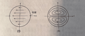 Figure 2-18
As shown in Figure 2-19, near the electrode of the measuring tube, the magnetic induction intensity B(z) is a stable value with a certain range;
At both ends of the measuring tube, B(z) weakens sharply. Therefore, the induced potential near the electrode is relatively large, and gradually weakens at both ends, and finally drops to zero. In this way, the electric field inside the fluid is not uniform, causing eddy currents to be generated on the X-Z parallel planes.
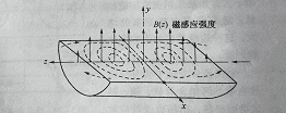 Figure 2-19
The eddy current mentioned above is generated under an alternating magnetic field. The size of the eddy current and the resistivity of the material is beautiful. The higher the resistivity, the smaller the eddy current generated (like the iron core of the iron core coil. In order to reduce the eddy current, high resistivity silicon is added to the iron core material).
Therefore, considering the eddy current, the metal conduit of the measuring tube should be made of high-resistivity, non-magnetic austenitic stainless steel material or non-metallic high-purity alumina industrial ceramic material. Due to the eddy current, there are also certain restrictions on the application of AC excitation to measure the conductivity of the fluid medium. A metal object with very high conductivity in a magnetic field will generate a large amount of eddy current, which will cause a large eddy current loss. For this reason, the measurement of liquid metal mostly uses a DC magnetic field or a water permanent magnetic field. Because they do not have electromagnetic induction, there will be no eddy currents. It can be analyzed that the phase difference between the eddy current under the alternating magnetic field and the flow-induced electric potential is 90°, which is the cause of the orthogonal interference. For rectangular wave excitation sensors, the eddy current waveform is in the state of star differentiation, which is orthogonal to the integral state of the flow signal.
In any case, it can be seen from Figure 2-18 and Figure 2-19 that the eddy current directly affects the output flow signal.