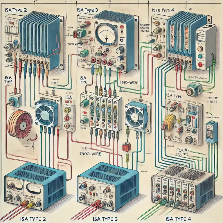
Current output transmitters are widely used in industrial applications to convert physical quantities such as pressure, temperature, or flow into a standardized electrical signal (usually 4-20mA). These devices are typically classified into three wiring configurations: two-wire, three-wire, and four-wire. Properly wiring a current output transmitter is essential to ensure accurate signal transmission and prevent potential malfunctions.

1. Two-Wire Current Output Transmitter
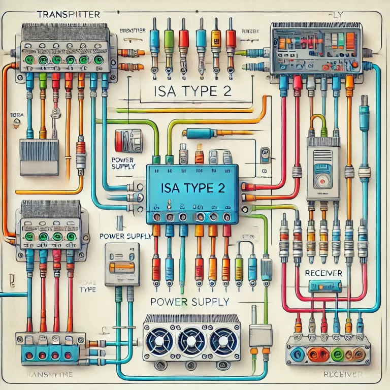
A two-wire transmitter is the most common type, especially in industrial environments due to its simplicity and cost-efficiency. It only requires two wires for both power supply and signal transmission.
Wiring Procedure:
- Power Supply (+): One wire connects the transmitter’s positive terminal (marked as “+”) to the positive terminal of the power supply. The power supply is typically a 24V DC source.
- Signal and Ground (-): The second wire connects the transmitter’s negative terminal (marked as “-“) to both the negative terminal of the power supply and the signal input of the control system (such as a PLC or data acquisition system). The loop includes the receiving device, which measures the 4-20mA current signal.
In this configuration, the current loop must be closed for the system to function correctly. The transmitter’s signal is directly proportional to the measured process variable (e.g., temperature, pressure). The two-wire transmitter consumes a small amount of power from the loop current itself, hence why the current output begins at 4mA instead of 0mA, leaving some margin for power supply.
Advantages:
- Cost-effective.
- Simple to wire.
- Ideal for long-distance signal transmission since current signals are less affected by resistance and voltage drops over long cables.
Example Wiring Setup:
  +24V DC --------------[+ TRANSMITTER]

                        [- TRANSMITTER] -------------- [PLC INPUT]

[24V GROUND] ----------------- [PLC GROUND] 
2. Three-Wire Current Output Transmitter
The three-wire configuration separates the power supply and signal wiring, providing an independent path for the signal current, which can be helpful for reducing noise or interference in certain applications.
Wiring Procedure:
- Power Supply (+): Connect the positive terminal of the power supply to the positive terminal of the transmitter (marked “+”).
- Power Ground (-): Connect the negative terminal of the power supply to the ground terminal of the transmitter.
- Signal Output: The signal wire connects from the transmitter’s output terminal (marked “OUT”) to the signal input terminal on the receiving device (such as a PLC or controller). This wire will carry the 4-20mA signal.
The ground wire is independent of the signal wire in this setup, and the three-wire configuration provides better signal isolation compared to the two-wire setup. This type is commonly used when the transmitter and the signal receiving device are located relatively close to each other.
Advantages:
- Improved signal isolation.
- Suitable for applications requiring separate power and signal grounds.
- Less sensitive to electrical noise.
Example Wiring Setup:
  +24V DC -------------[+ TRANSMITTER]

                        [GROUND] --------------------- [24V GROUND]

[SIGNAL OUT] ----------------- [PLC INPUT] 
3. Four-Wire Current Output Transmitter
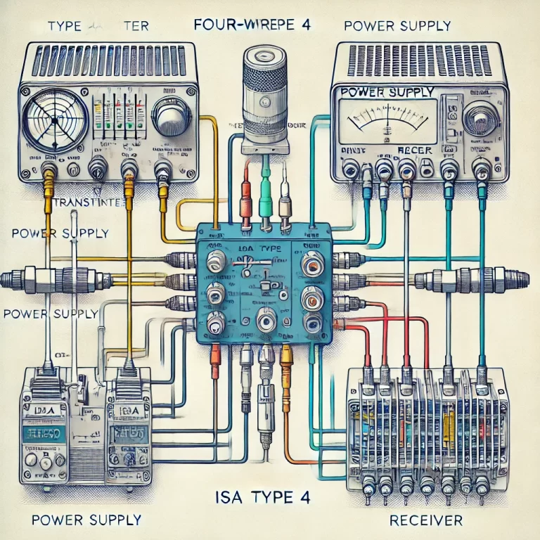
A four-wire transmitter uses two wires for power supply and two separate wires for the current signal output. This setup offers the highest level of isolation between the power and signal circuits, making it suitable for critical or high-accuracy applications.
Wiring Procedure:
- Power Supply (+): Connect the positive terminal of the power supply to the positive power input terminal of the transmitter.
- Power Ground (-): Connect the negative terminal of the power supply to the negative power input terminal of the transmitter.
- Signal (+): Connect the signal output positive terminal to the signal input terminal of the control system or data logger.
- Signal (-): Connect the signal output negative terminal to the signal ground of the control system or data logger.
In this configuration, the power supply is entirely independent from the signal wires, and the 4-20mA current is transmitted solely through the signal wires. This separation is useful in environments with electrical noise or where high signal accuracy is required.
Advantages:
- Complete isolation between power and signal circuits.
- Suitable for high-accuracy or noise-sensitive applications.
- Reduces potential for electrical interference.
Example Wiring Setup:
+24V DC ----------------[+ POWER]
                           [- POWER] ------------------- [24V GROUND]
                           [+ SIGNAL] ------------------ [PLC INPUT]
[- SIGNAL] ------------------ [PLC GROUND] 
Key Considerations When Wiring Current Output Transmitters
1. Power Supply Voltage:
Make sure that the power supply meets the transmitter’s specifications. Most current output transmitters operate on 24V DC, but it’s important to verify the required supply voltage from the transmitter’s datasheet to avoid under- or over-voltage situations.
2. Load Impedance:
For 4-20mA transmitters, it’s essential to maintain the load impedance (the total resistance in the loop) within the allowable range. Excessive impedance can reduce the current in the loop, leading to inaccurate measurements.
3. Cable Length and Resistance:
When installing transmitters over long distances, be mindful of voltage drops across the wires due to their resistance. Since the current signal remains constant, the voltage drop won’t affect the signal, but the transmitter’s power supply must provide sufficient voltage to compensate for these losses.
4. Noise and Signal Interference:
Current signals are generally less susceptible to electrical noise than voltage signals. However, in electrically noisy environments, using shielded cables and proper grounding techniques can further reduce interference.
5. Polarity:
Always ensure correct polarity when connecting the wires. Incorrect wiring can result in malfunction or damage to the transmitter.

Conclusion
Wiring a current output transmitter correctly is crucial for accurate and reliable signal transmission. The two-wire configuration is common for simple installations, while the three-wire and four-wire setups provide better isolation and noise immunity for more sensitive applications. By understanding the wiring requirements and following the proper procedures, you can ensure that your current output transmitter performs optimally in any industrial setting.
