Grounding electrodes are a crucial component in control systems, ensuring electrical safety and system stability. Proper installation and maintenance of grounding electrodes help protect equipment from electrical surges, prevent hazardous electric shocks, and ensure reliable system performance. This article provides a detailed step-by-step guide on how to construct effective grounding electrodes for control systems.
1. Choosing the Right Grounding Material
The first step in constructing a grounding electrode is selecting the appropriate material. Common materials used for grounding electrodes include:
- Copper: Copper is an excellent conductor of electricity and is highly resistant to corrosion, making it one of the most commonly used materials for grounding electrodes. However, it can be more expensive than other materials.
- Galvanized Steel: Steel electrodes are coated with zinc to protect against corrosion. These are more cost-effective than copper but might not last as long in certain environmental conditions.
- Copper-Clad Steel: A combination of copper and steel, copper-clad steel electrodes offer a good balance of conductivity, corrosion resistance, and cost.
The material chosen for the grounding electrode should have good conductivity, high resistance to corrosion, and be durable enough for the expected environmental conditions.
2. Designing the Grounding Electrode
The design of the grounding electrode should meet certain standards to ensure it is effective. Here are some key design considerations:
- Length and Depth: Grounding electrodes are typically buried at a depth of 2 to 3 meters (6 to 10 feet) to ensure stable contact with the earth. The electrode’s length usually ranges from 2 to 4 meters (6 to 12 feet), depending on the type of soil and environmental conditions.
- Soil Conditions: The soil’s electrical resistivity will significantly impact the electrode’s performance. Softer, wetter, or saline soils generally provide better conductivity than dry, rocky, or clay-rich soils. In poor soil conditions, a longer electrode may be required.
- Grounding Resistance: The resistance of the grounding system must meet safety standards, typically below 4 ohms in most cases. In some high-sensitivity environments, the resistance requirement may be stricter.
3. Selecting the Installation Location
The location of the grounding electrode is vital for its performance. Ideally, the electrode should be placed in an area with the following characteristics:
- Separation from High-Voltage Sources: The electrode should be installed at a safe distance from high-voltage equipment and power sources to prevent interference.
- Dry and Moisture-Controlled Soil: For optimal grounding, the electrode should be installed in soil that remains moist, as moisture improves conductivity. In dry areas, materials like salt or gypsum can be added around the electrode to enhance soil conductivity.
- Safe Distance from Buildings and Structures: Avoid placing electrodes near buildings, roads, or other infrastructure to prevent accidental damage or interference.
4. Methods of Installing Grounding Electrodes
There are several common methods for installing grounding electrodes, depending on the site conditions and the type of electrode used:
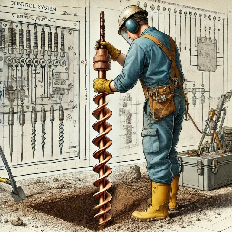
- Vertical Installation: The most common installation method is to bury the electrode vertically into the ground. A hole is dug, and the electrode is driven into the earth using a mechanical auger or manual tools. This method is effective in most soil conditions.
- Horizontal Installation: In certain situations where vertical installation is not feasible (e.g., rocky or shallow soil), a horizontal installation may be used. This involves laying the grounding electrode along the surface of the soil, typically at a depth of around 0.5 to 1 meter.
- Ring or Radial System: For larger systems or areas with particularly high electrical loads, a ring or radial grounding system may be used. This involves laying several electrodes in a loop or radial pattern to provide multiple grounding points, thus reducing the overall system resistance.

5. Connecting the Grounding Conductors
Once the grounding electrode is installed, the next step is to connect it to the control system using grounding conductors (wires). Key considerations for this step include:
- Conductor Material: Copper is the most commonly used conductor material due to its high conductivity and durability. However, aluminum can also be used in some situations where cost is a concern.
- Conductor Size: The size of the conductor depends on the size of the electrical system and the maximum fault current expected. For control systems, a conductor with an appropriate cross-sectional area (usually no smaller than 6 mm²) should be used.
- Connection Method: The conductor should be securely attached to the electrode using mechanical connectors such as clamps or lugs. Ensure that the connection is tight and corrosion-resistant to prevent any contact resistance or failure.
6. Corrosion Protection
Corrosion is one of the biggest threats to the longevity and effectiveness of grounding electrodes. Therefore, taking measures to protect the electrode from corrosion is critical:
- Protective Coatings: Many electrodes are coated with a protective layer to prevent corrosion. Galvanized steel, for example, is coated with zinc to provide protection. Copper electrodes naturally resist corrosion but can be coated with a corrosion-resistant layer if required.
- Wrapping and Enclosure: Some grounding systems may include an additional layer of wrapping around the electrode, such as plastic sheaths or tar-based coatings, which help reduce the risk of corrosion from soil or moisture exposure.

7. Testing and Verification
After installation, it is essential to test the grounding system to ensure it meets the required performance standards. The following tests are typically conducted:
- Ground Resistance Measurement: Using a ground resistance tester (often referred to as an earth resistance meter), the resistance between the grounding electrode and the earth is measured. The system should have a resistance value lower than the required standard, typically below 4 ohms.
- Continuity Test: Ensure there is a continuous connection between the grounding electrode and the control system. Any breaks or poor connections can result in dangerous system failures.
8. Maintenance and Inspection
Regular maintenance and inspection of the grounding system are essential for long-term performance:
- Visual Inspections: Check for any visible signs of wear, corrosion, or damage to the grounding system, including connections and electrodes.
- Resistance Testing: Periodically test the ground resistance, especially if environmental conditions change (e.g., after heavy rainfall, construction, or soil changes).
- Cleaning and Repairs: Clean any corrosion from connections and replace any damaged components.

Conclusion
Properly constructing and maintaining grounding electrodes for control systems is essential to ensure the safety and stability of electrical equipment. By following the steps outlined above, including selecting the right materials, designing the system appropriately, and testing its effectiveness, you can minimize the risk of electrical hazards and enhance system reliability. Always adhere to local standards and regulations when designing and implementing grounding systems, as they are essential for protecting both equipment and personnel.