1. Introduction
In modern industrial automation and process control, redundant sensors are widely deployed to enhance system reliability and safety.
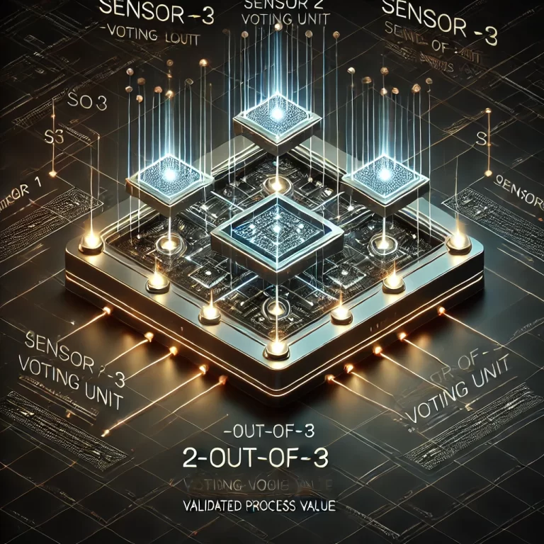
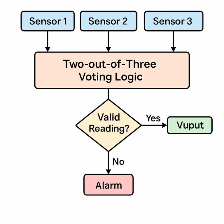
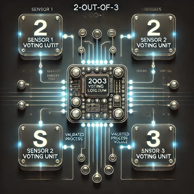
For critical measurement parameters—such as temperature, pressure, and liquid level—two-out-of-three voting logic (2oo3) is commonly used. This architecture employs three independent sensors measuring the same variable and determines the valid reading when at least two sensors agree, ensuring continuity and fault tolerance.
However, signal desynchronization between these redundant channels can lead to incorrect logic decisions, false alarms, or delayed system responses. Causes range from sensor response time differences to sampling delays and electromagnetic interference (EMI). Therefore, designing an effective desynchronization alarm logic is crucial to detect such anomalies promptly and accurately.
2. Overview of the 2oo3 Redundant System
2.1 Principle of Redundancy
A 2oo3 system continuously monitors the outputs from three independent sensors.
If one sensor fails, the other two can still produce a valid result.
The system votes on the readings, selecting the value agreed upon by at least two channels.
This design significantly improves fault tolerance by preventing single-point failures from causing total system shutdown.
2.2 Common Causes of Signal Desynchronization
Sensor Response Time Differences – Even identical model sensors may respond differently to a process change.
Sampling Time Mismatch – Slight offsets in data acquisition timing can cause inconsistent readings at the same physical moment.
Data Transmission Delays – Longer cable runs, network latency, or protocol buffering can introduce timing discrepancies.
Electromagnetic Interference (EMI) – Industrial noise may cause short-term signal spikes or drops.
3. Desynchronization Alarm Logic Design
3.1 Difference Calculation and Thresholds
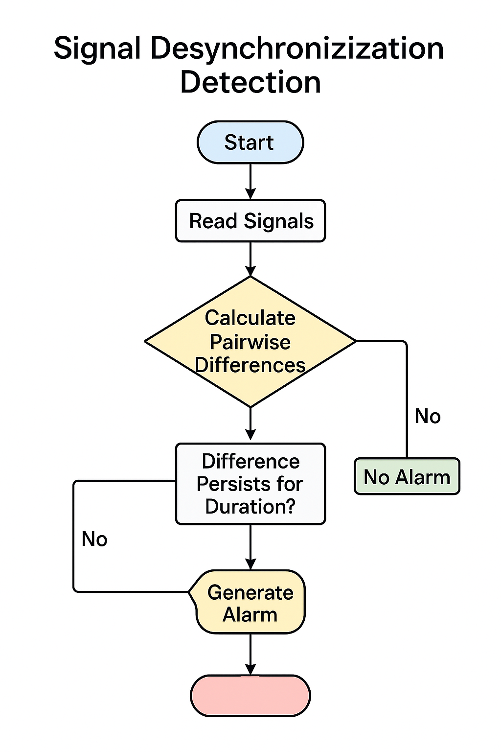
Calculate the absolute differences between each pair of sensor readings:
(S1-S2),(S2-S3),(S1-S3).Compare these differences against a preset threshold (Δ).
If the difference exceeds Δ, it may indicate desynchronization.
3.2 Duration Threshold
To avoid false alarms caused by transient disturbances:
Apply a persistence filter: only trigger an alarm if the difference remains above Δ for a continuous period T (e.g., 500 ms to 3 s depending on process requirements).
3.3 Deadband (Hysteresis)
Introduce a deadband zone to ignore small fluctuations caused by sensor accuracy limits or noise.
Alarm activation occurs only when the difference exceeds Δ + deadband, and it clears only when the difference drops below Δ – deadband.
3.4 Lag Compensation
In processes with known delays (e.g., slow sensor response or network lag), apply compensation algorithms to align signal timing before comparison.
4. Advanced Optimization and Engineering Practices
4.1 Alarm Severity Levels
Warning Level – Minor deviation for short duration; log event, monitor trend.
Fault Level – Significant deviation for sustained period; initiate corrective actions.
4.2 Adaptive Thresholds
Thresholds may be relaxed during sensor commissioning or start-up phases.
Over time, the system can automatically tighten limits based on stable operation trends.
4.3 Sensor Drift Detection & Self-Calibration
Compare each sensor periodically against a known reference.
Apply drift compensation to prevent long-term bias from causing false desynchronization alarms.
5. Engineering Application Examples
5.1 Nuclear Power Plant Cooling System
Three temperature sensors monitor reactor cooling water.
EMI-induced fluctuations are filtered using Δ = 2°C and T = 1 s.
Only sustained deviations trigger fault alarms, preventing unnecessary reactor shutdowns.
5.2 Aircraft Engine Oil Pressure Monitoring
Three oil pressure sensors use dynamic Δ adjustment based on flight phase.
Lag compensation ensures accurate voting during rapid throttle changes.
Predictive monitoring detects degradation trends for proactive maintenance.
6. Conclusion
An effective 2oo3 signal desynchronization alarm logic should integrate:
Pairwise difference calculation
Persistence filtering
Deadband control
Lag compensation
Adaptive thresholds and drift correction
With the integration of intelligent monitoring and predictive analytics, future redundant measurement systems will be able to self-adjust alarm parameters, improving both fault detection speed and operational reliability.