In practical applications, the naming relationship between DCS system tag numbers (logical points in the control room) and field instrument tag numbers (physical device labels) typically follows international standards (such as ISA S5.1) or factory-specific conventions. Below are common categories and examples:
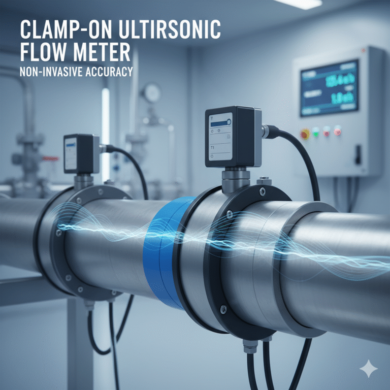
1. Flow Measurement Instruments
Field Instrument Tag: FT101 (Flow Transmitter)
DCS Tag:
FIC101: Flow Indicating Controller (PID control)
FI101: Flow Indication (display only)
FV101: Flow Control Valve (controlled by FIC101)
Corresponding Relationships:
FT101 → FIC101 or FI101
FV101 → Controlled by FIC101
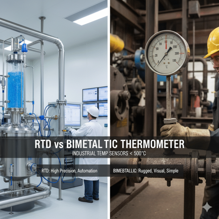
2. Temperature Measurement Instruments
Field Instrument Tag: TT201 (Temperature Transmitter)
DCS Tag:
TIC201: Temperature Indicating Controller (automatic control)
TI201: Temperature Indication (display only)
TSH201: High Temperature Alarm Switch
Corresponding Relationships:
TT201 → TIC201 or TI201
TSH201 → Triggers Alarm TIAH201
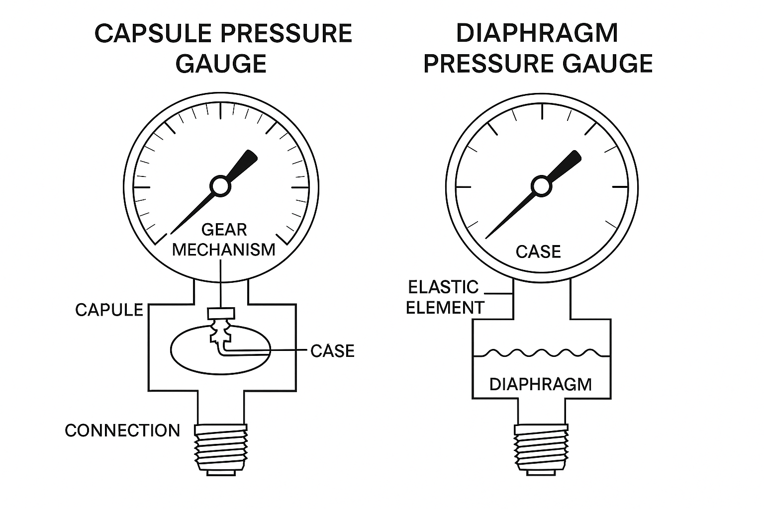
3. Pressure Measurement Instruments
Field Instrument Tag: PT301 (Pressure Transmitter)
DCS Tag:
PIC301: Pressure Indicating Controller
PI301: Pressure Indication (display only)
PSL301: Pressure Low Interlock Switch
Corresponding Relationships:
PT301 → PIC301 or PI301
PSL301 → Interlock Signal PISL301
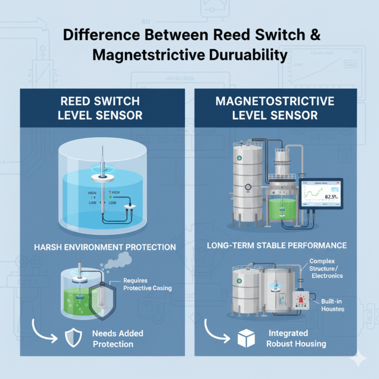
4. Level Measurement Instruments
Field Instrument Tag: LT401 (Level Transmitter)
DCS Tag:
LIC401: Level Indicating Controller
LI401: Level Indication (display only)
LAH401: High Level Alarm
Corresponding Relationships:
LT401 → LIC401 or LI401
LSH401 → Triggers Alarm LAH401
5. Analytical Instruments
Field Instrument Tag: AT501 (pH Transmitter)
DCS Tag:
AI501: Analytical Indication
AIC501: Analytical Indicating Controller (e.g., pH auto dosing)
Corresponding Relationships:
AT501 → AIC501 or AI501
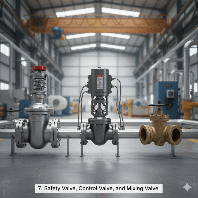
6. Control Valves and Switches
Field Valve Tag: FV102 (Flow Control Valve)
DCS Tag:
FV102: Valve Position Control Signal
ZV102: Valve Open/Closed Status
Key Rules Summary
Function Code Extension:
Field instruments focus on measurement and actuation (e.g., FT, TT, FCV).
DCS tags focus on control and indication (e.g., FIC, TIC, FI).
Signal Layering:
Transmitters (e.g., FT) → Input Signals (e.g., FIC or FI).
Valves (e.g., FV) → Output Signals (e.g., FV).
Alarms and Interlocks:
Switches (e.g., LSH, PSL) → DCS Alarm Points (e.g., LAH, PISL).
Control Loop Parameters Abbreviations
PV (Process Variable): Real-time measured value (e.g., temperature, pressure).
Example: PV = 150°C.
SV (Set Value): Control setpoint.
Example: SV = 160°C.
MV (Manipulated Variable): Controller output signal (e.g., valve position).
Example: MV = 65%.
OP (Output): Same as MV, controller output.
Example: OP = 75%.

Common DCS Abbreviations
PID (Proportional Integral Derivative): Control algorithm.
Example: P = 2.0, I = 30s, D = 5s.
AI (Analog Input): Analog input signal (e.g., 4-20mA).
Example: AI101.
AO (Analog Output): Analog output signal (e.g., control valve position).
Example: AO201.
DI (Digital Input): Digital input (e.g., equipment status).
Example: DI301 = ON.
DO (Digital Output): Digital output (e.g., start command).
Example: DO401 = START.
HH/LL (High-High/Low-Low): High-high and low-low alarms.
Example: PV = 10 MPa triggers emergency interlock when it exceeds HH = 9.5 MPa.

Practical Control Loop Example
For the flow control loop FIC101:
PV: Real-time flow value from FT101 (e.g., PV = 45 m³/h).
SV: Target flow (e.g., SV = 50 m³/h).
MV: Control output to FV101 (e.g., MV = 60%).
PID Parameters: Adjust P, I, D to stabilize PV near SV.
Abbreviations Summary
| Abbreviation | Full Name | Function Description | Example |
|---|---|---|---|
| PV | Process Variable | Real-time measurement value | PV = 120°C |
| SV | Set Value | Control target value | SV = 150°C |
| MV | Manipulated Variable | Controller output signal | MV = 70% |
| PID | Proportional Integral Derivative | Control algorithm | P = 2.0, I = 30s, D = 5s |
| AI | Analog Input | Analog input signal | AI101 |
| AO | Analog Output | Analog output signal | AO201 |
| DI | Digital Input | Digital input | DI301 = ON |
| DO | Digital Output | Digital output | DO401 = START |
