
How to Choose the Right Mass Flow Meter Without Overspending
Mass flow measurement plays an important role in industrial process control, energy management, chemical processing, and custody transfer applications.
When selecting a mass flow meter, engineers often encounter two technologies: Coriolis mass flow meters and thermal mass flow meters.
Although both instruments provide mass flow measurements, they operate on fundamentally different principles.
A Coriolis flow meter measures mass flow directly by detecting the effects of fluid movement on vibrating measuring tubes. A thermal mass flow meter determines gas mass flow through heat transfer between a heated sensor and the flowing gas.
These differences affect measurement accuracy, installation requirements, pressure loss, maintenance, and overall project costs.
Choosing the wrong technology may result in unnecessary equipment expenditure, measurement instability, or poor performance under actual operating conditions.
This article explains how both technologies work, compares their advantages and limitations, and provides practical guidance for industrial flow meter selection.
1. How Does a Coriolis Mass Flow Meter Work?
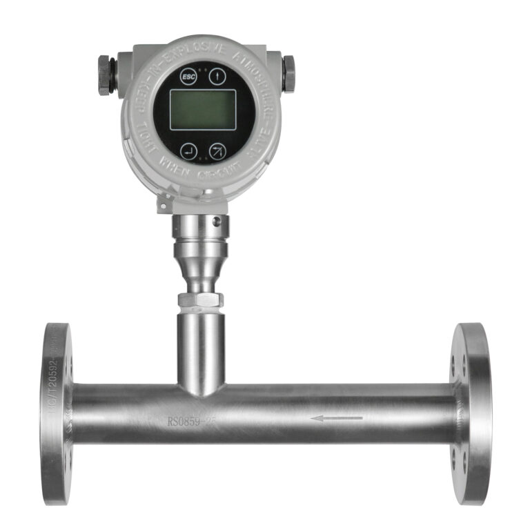
A Coriolis mass flow meter operates according to the Coriolis effect, which occurs when mass moves through a vibrating system.
Inside the flow meter, one or more measuring tubes are driven into controlled oscillation by an electromagnetic excitation system.
When fluid passes through these vibrating tubes, Coriolis forces cause a small difference in the motion of the inlet and outlet sections.
Sensors detect this difference, typically expressed as a phase or time delay.
The transmitter converts the measured signal into mass flow rate using the instrument’s calibration characteristics.
Unlike volumetric flow measurement technologies, Coriolis meters directly measure mass flow without requiring a separate density measurement to calculate mass flow from volumetric flow.
Additional Measurement Capabilities
Many Coriolis flow meters can simultaneously provide:
- Mass flow rate
- Fluid density
- Process temperature
- Calculated volumetric flow rate
- Accumulated mass and volume
Density is generally determined from the measuring tube’s resonant characteristics, while temperature is measured using an integrated temperature sensor.
Main Advantages
High measurement accuracy
Many industrial Coriolis flow meters offer liquid mass flow accuracy in the range of approximately +/-0.1% to +/-0.5% of reading under specified reference conditions. Actual specifications vary by manufacturer, model, medium, and operating range.
Direct mass measurement
The instrument does not require an external density transmitter to obtain mass flow.
Multiple process variables
A single instrument can provide mass flow, density, and temperature information.
Broad application range
Coriolis technology can be applied to many liquids, gases, high-viscosity materials, and certain slurry applications, provided the meter is correctly selected.
Main Limitations
Despite these advantages, Coriolis meters are not suitable for every application.
Potential limitations include:
- Higher initial purchase cost
- Increasing equipment size and cost for large pipelines
- Pressure loss through the measuring tubes
- Sensitivity to excessive mechanical stress or vibration
- Measurement difficulties with entrained gas or unstable two-phase flow
- Possible wear or plugging in certain slurry applications
For high-viscosity liquids, engineers must also evaluate pressure loss and available pumping capacity.
Engineering takeaway: Coriolis flow meters are particularly attractive when high accuracy, direct mass measurement, or simultaneous density measurement is required.
2. How Does a Thermal Mass Flow Meter Work?
A thermal mass flow meter measures gas flow based on heat transfer.
A typical thermal dispersion sensor contains a heated temperature-sensitive element and a reference temperature sensor.
As gas flows across the sensor, it removes heat from the heated element.
The amount of heat transferred depends on gas flow conditions and the thermal properties of the gas.
In a constant-temperature-difference design, the electronics adjust the heating power to maintain a specified temperature difference between the heated and reference elements.
The transmitter then converts the measured heat-transfer response into mass flow using a calibration relationship.
Importantly, this relationship is not universally linear. It depends on sensor design, gas properties, calibration conditions, and operating range.
Why Thermal Mass Flow Meters Are Popular
Thermal mass flow technology offers several advantages for industrial gas measurement.
Direct indication of gas mass flow
The instrument can report mass flow or standardized volumetric flow without requiring a separate pressure and temperature transmitter for conventional compensation calculations.
However, accurate results still depend on the gas composition and calibration conditions.
Low pressure loss
Insertion-type thermal mass flow meters introduce relatively little obstruction into the pipeline.
Economical measurement in large pipelines
For large-diameter gas pipelines, insertion-type thermal meters can be substantially more economical than large Coriolis meters.
Suitable for gas consumption monitoring
Common applications include compressed air, nitrogen, process gas, and selected industrial gas monitoring systems.
Main Limitations
Thermal mass flow meters are sensitive to factors that influence heat transfer.
These include:
- Changes in gas composition
- Moisture and condensation
- Oil mist or liquid droplets
- Dust accumulation and sensor contamination
- Incorrect insertion depth
- Distorted velocity profiles
- Calibration mismatch
Thermal flow meters are primarily designed for gas measurement. They should not be treated as general replacements for Coriolis meters in liquid applications.
Engineering takeaway: Thermal mass flow meters are often a cost-effective choice for gas monitoring when the gas properties are sufficiently stable and the installation conditions are suitable.
3. Coriolis vs. Thermal Mass Flow Meters: Key Differences
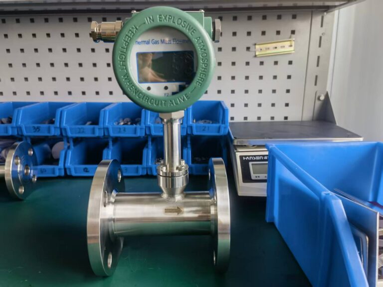
| Comparison | Coriolis Mass Flow Meter | Thermal Mass Flow Meter |
|---|---|---|
| Measurement principle | Coriolis forces in vibrating tubes | Heat transfer from a heated sensor |
| Measurement approach | Direct mass measurement | Gas flow derived from thermal response and calibration |
| Typical media | Liquids, gases, selected slurries | Primarily gases |
| Typical accuracy | High; often +/-0.1% to +/-0.5% for liquids | Commonly around +/-1% to +/-2.5%, depending on accuracy basis |
| Density measurement | Available on many models | Generally unavailable |
| Pressure loss | Depends on meter size and tube design | Usually low, particularly for insertion types |
| Straight pipe requirements | Often limited for single-phase flow | Generally more demanding |
| Gas composition sensitivity | Usually lower for direct mass measurement | Can be significant |
| Two-phase flow | May cause substantial measurement problems | Liquid droplets can disturb measurement |
| Large-pipe economics | Often expensive | Insertion types often economical |
| Main applications | Precision process measurement, batching, selected custody transfer | Gas consumption and energy monitoring |
Important: The performance ranges above are indicative rather than universal specifications. The manufacturer’s technical data must be checked for the actual model and operating conditions.
4. Understanding Measurement Accuracy: Reading vs. Full Scale
When comparing mass flow meters, engineers should not evaluate accuracy percentages without checking how those percentages are defined.
Two common accuracy expressions are:
- Percentage of reading (% of reading)
- Percentage of full scale (% FS)
These specifications can produce very different measurement uncertainties.
Example: A Gas Flow Meter with a 0–1000 Nm3/h Range
Assume the actual flow is 100 Nm3/h.
Meter A: +/-1% of reading
Allowable error at this operating point:
Error = 100 * 1% = +/-1 Nm3/h
Meter B: +/-1% of full scale
Allowable error:
Error = 1000 * 1% = +/-10 Nm3/h
Although both meters are advertised as having 1% accuracy, their error limits at the operating point are significantly different.
This distinction becomes especially important when measuring low flow rates.
What About Turndown Ratio?
Turndown ratio describes the relationship between the maximum and minimum flow rates over a specified operating range.
For example:
A meter with a specified measuring range of 10–1000 kg/h has a turndown ratio of 100:1.
However, a wide detectable flow range does not necessarily mean that the instrument maintains its best accuracy throughout the entire range.
Coriolis meters can be affected by zero stability at low flow rates.
Thermal mass flow meters may also experience increasing relative measurement uncertainty at the lower end of the range.
Selection recommendation: Always compare the guaranteed accuracy at the customer’s actual minimum, normal, and maximum flow rates rather than relying on a single percentage in the product brochure.
5. How Gas Composition and Process Conditions Affect Measurement
The influence of process conditions is one of the most important differences between Coriolis and thermal mass flow meters.
5.1 Gas Composition Changes
Thermal mass flow measurement depends on the thermal properties of the gas.
If the instrument is calibrated for nitrogen but is subsequently used for a different gas mixture, the measurement may become inaccurate unless suitable correction factors or calibration data are available.
Similarly, changes in the methane and carbon dioxide concentrations of biogas may affect the measurement response.
A Coriolis meter measures mass flow through the mechanical response of the vibrating measuring tubes.
Its mass flow measurement is therefore generally less dependent on gas composition.
However, gas density, pressure loss, operating pressure, and the instrument’s gas measurement capability must still be considered.
5.2 Moisture and Condensation
Liquid droplets and condensation can substantially disturb thermal gas flow measurement.
A liquid droplet contacting a heated sensor may temporarily increase heat removal, creating an abnormal signal.
Repeated condensation may also lead to contamination or deposits on the probe.
Coriolis meters also have limitations with multiphase flow.
For example, entrained gas bubbles in a liquid may cause measurement instability or errors.
Neither technology should automatically be considered suitable for uncontrolled gas-liquid two-phase flow.
5.3 Dirty or Dust-Laden Gas
Dust, oil deposits, and other contaminants may accumulate on thermal sensor surfaces.
This changes heat transfer characteristics and can introduce measurement errors.
Specialized thermal probes may be suitable for some contaminated gas applications, but their suitability must be evaluated individually.
For Coriolis meters, abrasive particles can cause measuring tube wear, while deposits may affect measurement performance.
Practical Recommendation
Before selecting either technology, confirm:
- Actual gas or liquid composition
- Minimum and maximum process temperatures
- Operating pressure
- Moisture or condensation risk
- Presence of solids or contaminants
- Required accuracy under real operating conditions
6. Installation Requirements: Common Mistakes to Avoid
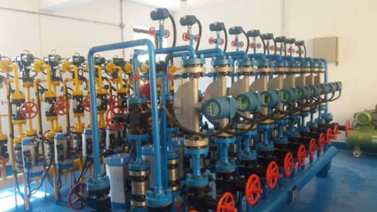
Even a correctly selected flow meter may provide inaccurate measurements if it is installed improperly.
6.1 Coriolis Mass Flow Meter Installation
Avoid excessive pipe stress
The instrument should not be used to force misaligned piping into position.
Excessive installation stress may affect zero stability or cause mechanical damage.
Use appropriate pipe supports and follow the manufacturer’s mounting instructions.
Evaluate external vibration
Strong vibration from pumps, compressors, or nearby equipment may interfere with the sensor.
Provide adequate support and assess vibration conditions before installation.
Flexible connections should not be added automatically without considering their effects on the mechanical installation.
Maintain appropriate process conditions
For liquid measurement, avoid gas accumulation in the measuring tubes.
For gas measurement, minimize the possibility of condensate collecting inside the sensor.
For certain curved-tube designs, a downward tube orientation may be recommended for liquids, while an upward orientation may be preferred for gases.
However, installation orientation must always follow the instructions for the specific sensor design.
Perform zero verification correctly
Where required by the manufacturer, zero adjustment should be performed under stable, no-flow conditions with the measuring tubes properly filled.
Do not perform an unnecessary zero adjustment simply because the measured flow appears incorrect.
First check the process conditions and diagnostic information.
6.2 Thermal Mass Flow Meter Installation
Provide adequate straight pipe lengths
Thermal mass flow meters can be sensitive to distorted flow profiles.
Depending on the product and upstream disturbances, an installation may require 10D–20D or more of upstream straight pipe.
Requirements after elbows, control valves, reducers, or other disturbances may be different.
Use the manufacturer’s installation guidance rather than assuming one universal straight-pipe requirement.
Check insertion depth
For insertion-type meters, the sensor must be positioned according to the manufacturer’s specified insertion depth.
Some designs measure near the pipe center, while others use a different calibrated sensing position.
Incorrect insertion depth can cause systematic measurement errors.
Avoid condensation and contamination
Where possible, choose an installation position that minimizes liquid accumulation and contamination.
Provide upstream filtration or gas treatment when required by the actual process conditions.
The filter type and filtration rating must be determined from the application’s requirements rather than applying one fixed specification to every installation.
Confirm gas calibration settings
Ensure the meter is configured for the correct gas or gas mixture.
When gas composition changes significantly, a new calibration, suitable correction method, or alternative measurement technology may be necessary.
7. How to Choose the Right Mass Flow Meter
A practical selection process should consider the medium, measurement purpose, operating conditions, and total project cost.
Step 1: Identify the Fluid
For liquid mass flow measurement, Coriolis technology is often an appropriate starting point when direct mass measurement is required.
For clean, dry gases with relatively stable composition, thermal mass flow measurement may offer better cost efficiency.
For slurry applications or gases with changing composition, review the operating conditions carefully before choosing a technology.
Step 2: Define the Accuracy Requirement
Consider why the flow is being measured.
Applications involving precise chemical dosing, high-value liquid products, or demanding material balances may justify the additional cost of a Coriolis meter.
For compressed air consumption monitoring and general gas energy management, thermal mass flow measurement may provide sufficient performance at a lower cost.
Custody transfer applications require additional evaluation of applicable measurement standards, calibration, legal metrology, and contractual requirements.
Step 3: Evaluate Pipe Diameter and Pressure Loss
For large-diameter, low-pressure gas pipelines, insertion-type thermal mass flow meters are often financially attractive.
A Coriolis meter may introduce greater pressure loss and require higher installation expenditure.
For smaller pipelines requiring high-accuracy mass flow and density measurement, Coriolis technology may provide significant operational benefits.
Step 4: Evaluate Process Stability
Determine whether gas composition, moisture content, pressure, temperature, and flow conditions remain stable.
Thermal technology is particularly sensitive to changes affecting heat transfer.
Coriolis technology offers broader direct mass measurement capabilities, but it still requires stable and suitable process conditions.
Step 5: Calculate Total Cost of Ownership
Do not make the final decision based only on purchase price.
Include installation, pressure loss, maintenance, calibration, and long-term operational performance.
8. Cost Comparison: Which Technology Is More Economical?
The purchase price of a flow meter is only one component of the total measurement cost.
Initial Equipment Cost
Coriolis meters generally involve more complex mechanical sensor construction and electronics.
Their prices can increase considerably with pipeline diameter, pressure rating, material requirements, and accuracy specifications.
Thermal mass flow meters, especially insertion-type designs, are often more economical for large gas pipelines.
Installation Cost
Coriolis meters may require stronger pipe supports due to their weight and sensor design.
Thermal insertion meters may offer simpler mechanical installation, particularly when an appropriate process connection is already available.
However, thermal meters may require additional straight-pipe length, flow conditioning, or carefully selected installation locations.
Operating Cost
Pressure loss can affect operating energy consumption.
Coriolis meters may produce measurable pressure loss depending on their internal tube geometry and flow conditions.
Insertion-type thermal meters generally cause relatively little additional pressure loss.
Thermal sensors also consume electrical power for heating, although this is normally a relatively small part of overall industrial operating costs.
Maintenance and Calibration
Coriolis meters have no rotating measurement elements, but maintenance and verification may still be required.
Thermal probes may need inspection or cleaning where dust, oil, or other deposits are present.
Gas composition changes can also create additional calibration or configuration costs.
Total Cost of Ownership
A useful project-level calculation is:
TCO = Purchase Cost + Installation Cost + Operating Cost + Maintenance Cost + Calibration Cost
The appropriate operating period should be defined for the project, such as five or ten years.
The lowest purchase price does not always deliver the lowest total measurement cost.
A more expensive Coriolis meter may be justified when accuracy, density measurement, or process quality delivers measurable value.
Conversely, a thermal mass flow meter may provide the most economical solution when the objective is simply to monitor gas consumption.
9. Typical Industrial Applications
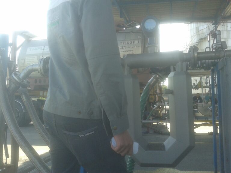
Case 1: Diesel Loading and Mass Measurement
Application: Diesel fuel transfer and loading.
Measurement objective: Accurate mass measurement for inventory control or loading operations.
Recommended technology to evaluate: Coriolis mass flow meter.
Coriolis technology can measure the mass of diesel directly and may also provide density and temperature data.
This is useful where the customer requires precise product quantity measurement.
However, the flow range, pressure loss, accuracy requirements, and applicable commercial measurement standards must be confirmed before final selection.
Case 2: DN200 Compressed Air Pipeline
Application: Factory compressed air consumption monitoring.
Measurement objective: Measure compressed air usage for energy management and internal cost allocation.
Recommended technology to evaluate: Insertion-type thermal mass flow meter.
In this application, the customer generally needs reliable consumption information rather than custody transfer accuracy.
A thermal mass flow meter can provide an economical solution with relatively low pressure loss.
Before selection, confirm the pipe dimensions, operating pressure, air quality, required flow range, and available straight-pipe lengths.
Case 3: Chemical Liquid Batching
Application: High-value chemical dosing and batching.
Measurement objective: Accurate mass flow control.
Recommended technology to evaluate: Coriolis mass flow meter.
Direct mass measurement helps reduce uncertainty associated with density variations.
Some Coriolis models can also provide density information for additional process monitoring.
The instrument must be compatible with the chemical, operating temperature, pressure, and viscosity.
Case 4: Biogas Flow Monitoring
Application: Biogas production or gas consumption monitoring.
Measurement objective: Monitor gas production and operating performance.
Recommended technology to evaluate: Application-specific thermal gas mass flow meter, subject to gas composition and moisture conditions.
Thermal meters are frequently considered for biogas applications.
However, changes in methane concentration, carbon dioxide content, and moisture can affect measurement accuracy.
If gas composition varies substantially or high-accuracy measurement is required, additional gas analysis, compensation, or an alternative metering technology may be necessary.
10. Common Problems and Troubleshooting
When a mass flow meter provides unstable, incorrect, or missing readings, troubleshooting should follow a structured procedure.
Problem 1: Coriolis Flow Reading Fluctuates
Possible causes:
- Entrained gas in the liquid
- Excessive external vibration
- Unstable process flow
- Improper pipe support
- Sensor or transmitter diagnostic alarms
Recommended checks:
- Check the transmitter’s diagnostic information.
- Confirm stable single-phase operating conditions.
- Inspect pipe supports and vibration sources.
- Verify that the sensor is properly filled.
- Check zero stability according to the manufacturer’s instructions.
Avoid performing repeated zero adjustments without identifying the underlying problem.
Problem 2: Thermal Mass Flow Reading Is Too High or Too Low
Possible causes:
- Incorrect gas calibration
- Gas composition changes
- Sensor contamination
- Incorrect insertion depth
- Disturbed flow profile
- Condensation on the sensing element
Recommended checks:
- Verify the gas selection and calibration settings.
- Inspect the sensor for contamination.
- Confirm insertion depth and flow direction.
- Check available straight-pipe lengths.
- Evaluate gas composition and moisture conditions.
Clean the probe only using the manufacturer’s approved procedure.
Problem 3: Flow Meter Displays Zero Despite Actual Flow
Possible causes:
- Incorrect wiring
- Power supply problems
- Incorrect output configuration
- Flow below the configured cutoff
- Sensor or transmitter faults
Recommended checks:
- Verify the power supply.
- Check transmitter alarms and status indicators.
- Inspect signal wiring and terminals.
- Verify flow cutoff and range settings.
- Confirm communication configuration where applicable.
For 4–20 mA signals, confirm loop wiring and available loop power.
For RS485 communication, check communication parameters, polarity, termination, and network configuration as applicable.
Problem 4: Measurement Changes After Maintenance
Possible causes:
- Changed installation stress
- Incorrect sensor reinstallation
- Modified gas configuration
- Incorrect zero adjustment
- Changed process conditions
Recommended checks:
Compare the installation, configuration, and operating conditions before and after maintenance.
Do not assume that the instrument requires recalibration until installation and process-related causes have been investigated.
11. Frequently Asked Questions
Q1: Is a Coriolis flow meter always more accurate than a thermal mass flow meter?
Not necessarily under every operating condition.
Coriolis technology generally offers higher accuracy for many liquid mass flow applications, but the actual performance depends on meter design, flow range, installation, and process conditions.
Always compare the specified accuracy at the intended operating point.
Q2: Can a thermal mass flow meter measure liquids?
Conventional industrial thermal dispersion mass flow meters are primarily designed for gases.
Specialized thermal measurement technologies exist for liquids, but a standard gas thermal mass flow meter should not be used for liquid measurement unless explicitly approved by the manufacturer.
Q3: Does a Coriolis flow meter require straight pipe lengths?
Many Coriolis meters have minimal straight-pipe requirements under suitable single-phase conditions.
However, proper support, installation orientation, mechanical stress control, and avoidance of problematic process conditions remain important.
Q4: Can a thermal mass flow meter measure different gases?
Some thermal meters support multiple calibrated gas selections or correction factors.
However, switching between gases without appropriate calibration or configuration may produce substantial errors.
The instrument must be suitable for the actual gas composition.
Q5: Which mass flow meter is better for compressed air?
For general compressed air consumption monitoring, thermal mass flow meters are often an economical choice.
For applications requiring particularly high accuracy or more demanding process measurement, other technologies, including Coriolis, may be evaluated.
The final choice depends on flow rate, pipeline size, pressure, accuracy, gas quality, and budget.
Q6: Which mass flow meter is better for large pipelines?
For large gas pipelines, insertion-type thermal mass flow meters often offer significant cost and installation advantages.
For liquid mass flow applications, Coriolis technology may be appropriate, but large-diameter equipment costs and pressure loss must be carefully evaluated.
12. Conclusion: Choose the Technology That Fits the Application
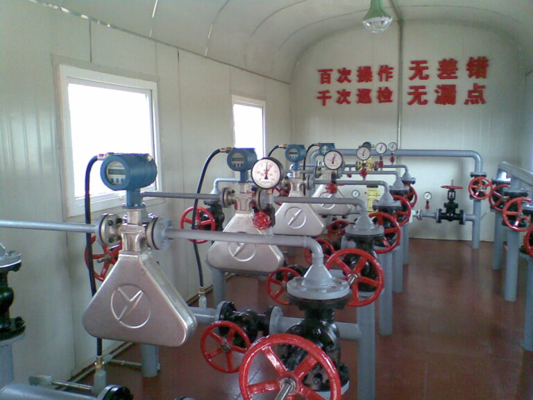
Coriolis and thermal mass flow meters both provide valuable solutions for industrial mass flow measurement, but their strengths are different.
Coriolis mass flow meters are particularly suitable for applications requiring direct mass measurement, high accuracy, density measurement, and precise process control.
Thermal mass flow meters are often an economical choice for gas consumption monitoring, compressed air systems, nitrogen distribution, and large-diameter gas pipelines.
The best technology is not necessarily the most expensive one.
A successful flow meter selection should begin with the medium, operating conditions, required accuracy, and measurement purpose.
Pipe diameter, installation limitations, pressure loss, maintenance requirements, and total cost of ownership should then be considered.
By evaluating these factors before purchasing, engineers can avoid unnecessary expenditure while achieving reliable long-term measurement performance.
Need Help Selecting the Right Mass Flow Meter?
At Dalian Zero Instrument Technology Co., Ltd., we help industrial customers evaluate flow measurement solutions for liquids, gases, and demanding process applications.
Whether you are considering a Coriolis mass flow meter for precise liquid measurement or a thermal mass flow meter for industrial gas monitoring, our team can assist with technical selection and application evaluation.
Website: https://zeroinstrument.com
Contact: [email protected]
Author: Michael Sun | Dalian Zero Instrument Technology Co., Ltd.
Suggested SEO Title: Coriolis vs. Thermal Mass Flow Meters: Accuracy, Cost & Selection Guide
Meta Description: Compare Coriolis and thermal mass flow meters by working principle, accuracy, installation, maintenance, and cost. Learn how to select the right flow meter.
Suggested URL Slug: coriolis-vs-thermal-mass-flow-meter
Focus Keywords: Coriolis vs thermal mass flow meter, Coriolis mass flow meter, thermal mass flow meter, mass flow meter selection, gas mass flow measurement.