
In industrial process control systems, control valves are critical devices for regulating flow, pressure, temperature, and level. A common problem encountered in chemical plants, power stations, oil & gas facilities, and water treatment systems is that the control valve command signal from the DCS does not match the actual valve position feedback signal.
Typical symptoms include:
- Large deviation between valve command and feedback position
- Valve position drifting or unstable feedback
- Static position error
- Slow response or valve not following the command
- DCS valve deviation alarm triggered
This article explains the common causes of control valve position feedback errors and provides a practical troubleshooting guide for field engineers.
1. How Does Control Valve Position Feedback Work?
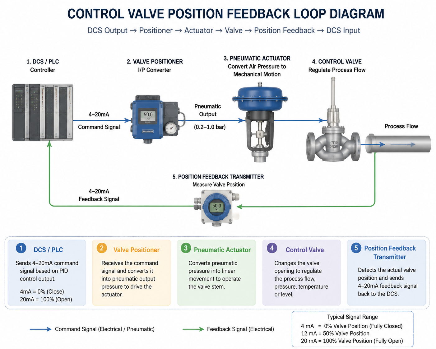
A typical pneumatic control valve position control loop consists of several components:
DCS Output → Positioner → Pneumatic Actuator → Valve Stem Movement → Position Feedback Transmitter → DCS Input
The DCS sends a 4–20mA command signal representing the required valve opening:
- 4mA = 0% valve position
- 12mA = 50% valve position
- 20mA = 100% valve position
The valve positioner converts the electrical signal into pneumatic output pressure to move the actuator. The position feedback device then measures the actual valve travel and sends a feedback signal back to the DCS.
When the command signal and feedback signal do not match, the problem can be located in the DCS system, signal loop, positioner, actuator, feedback sensor, or mechanical valve assembly.
2. Main Types of Control Valve Position Errors
Control valve feedback problems can generally be divided into two categories.
Type 1: Fixed Position Deviation (Static Error)
The valve can move normally, but the feedback always has a constant difference from the command.
Example:
- DCS command: 50%
- Actual valve position: 50%
- Feedback display: 45%
Possible causes:
- Feedback calibration error
- Incorrect position transmitter range
- LVDT zero/span drift
- DCS scaling mismatch
Type 2: Valve Does Not Follow the Command
The valve response is slow, unstable, or completely unable to reach the commanded position.
Typical symptoms:
- Command changes but valve does not move
- Valve stops at an incorrect position
- Feedback oscillates continuously
Possible causes:
- Insufficient air supply
- Positioner failure
- Mechanical sticking
- Actuator problems
3. Step-by-Step Troubleshooting Procedure
Step 1: Check the DCS Output Signal
First confirm whether the DCS output channel is working correctly.
Check AO (Analog Output) Signal
Measure the actual 4–20mA output at the cabinet terminal.
Example:
| DCS Command | Expected Output |
|---|---|
| 0% | 4mA |
| 50% | 12mA |
| 100% | 20mA |
If measured current matches the DCS command:
→ DCS output channel is normal.
If the current does not match:
Possible problems:
- AO card failure
- Loose terminal connection
- Short circuit
- Safety barrier failure
Step 2: Verify DCS Configuration
Check that the DCS configuration is correct:
- Command range and feedback range must be consistent
- 0–100% should correspond to 4–20mA
- Check signal filtering settings
- Check deadband settings
- Verify direct/reverse action configuration
Incorrect configuration may cause poor valve tracking performance.

4. Check Instrument Air Supply
For pneumatic control valves, air supply problems are one of the most common causes.
Check Air Pressure
Normal instrument air pressure:
0.4–0.6 MPa
Low or unstable air pressure may cause:
- Insufficient actuator force
- Valve unable to reach target position
- Permanent position deviation
Check Air Filter Regulator
Inspect:
- Filter blockage
- Drain condition
- Regulator output stability
A blocked filter or damaged regulator can reduce positioner performance.
5. Valve Positioner Troubleshooting
The valve positioner is one of the most frequent failure points.
5.1 Positioner Parameter Problems
Check:
- Zero calibration
- Span calibration
- Deadband setting
- Direct/reverse action
- Automatic stroke calibration
For smart positioners, perform automatic tuning:
Examples:
- ABB positioner
- Siemens SIPART
- Fisher DVC series
After calibration, verify that the valve can correctly follow the 4–20mA command.
5.2 Positioner Hardware Problems
Possible failures:
- Nozzle/flapper blockage
- Piezo valve sticking
- Internal pneumatic component failure
- Loose feedback linkage
- Excessive mechanical clearance
6. Check Valve Position Feedback Components
If the valve reaches the correct physical position but the DCS feedback is incorrect, focus on the feedback system.
Check:
Mechanical Connection
Possible problems:
- Loose feedback arm
- Damaged linkage
- Incorrect mounting position
- Excessive mechanical play
LVDT / Position Sensor
Possible failures:
- Zero drift
- Range drift
- Sensor damage
Feedback Signal Loop
Check:
- 4–20mA feedback wiring
- Terminal connection
- Safety barrier
- Input card
7. Check Actuator and Valve Mechanical Problems
Mechanical problems are common causes of valve position errors.
Possible causes:
Actuator Problems
- Damaged diaphragm
- Weak actuator spring
- Insufficient actuator force
Valve Body Problems
- Valve stem friction too high
- Packing gland tightened excessively
- Valve plug sticking
- Corrosion or deposits
- Crystallized process medium
Typical symptom:
The valve does not move at small signals but suddenly moves after reaching a higher command value.
This indicates a large mechanical dead zone.
8. Special Operating Conditions
Some process conditions can also cause valve position deviation.
High Differential Pressure
Large pressure imbalance across the valve may create excessive force on the valve plug.
Result:
- Actuator cannot overcome the force
- Valve cannot reach the required position
Incorrect Actuator Selection
Check:
- Air-to-open / air-to-close configuration
- Actuator thrust requirement
- Valve sizing
Solenoid Valve Interlock Problems
For valves equipped with solenoid valves:
Small internal leakage may disturb the positioner’s pneumatic output and affect valve stability.
9. Quick Fault Diagnosis Method
Example: Command = 50%
Observe the actual valve position.
Case 1:
Actual valve position = 50%
DCS feedback ≠ 50%
Possible fault:
→ Feedback transmitter / LVDT / feedback loop problem
Case 2:
Actual valve position = 35%
DCS command = 50%
Valve stops and cannot move further.
Possible fault:
→ Positioner, air supply, actuator, or mechanical sticking problem
10. Field Test Method
Disconnect the positioner input signal from the DCS.
Apply standard signals manually:
- 4mA
- 12mA
- 20mA
Observe valve travel locally.
This test can isolate the DCS system and directly verify the valve assembly performance.
11. Recommended Solutions
| Problem Area | Recommended Action |
|---|---|
| Signal wiring | Tighten terminals, repair wiring, check safety barrier |
| Instrument air | Clean filters, repair leaks, stabilize air pressure |
| Positioner | Perform auto-tuning, recalibrate zero/span |
| Feedback linkage | Adjust and tighten mechanical connections |
| Valve sticking | Isolate process, inspect and repair valve |
| DCS configuration | Correct scaling, filtering, and deadband settings |
| Hardware failure | Replace damaged positioner, sensor, AO card, regulator |
12. Preventive Maintenance
To avoid repeated control valve feedback problems:
- Perform valve stroke calibration during maintenance shutdowns
- Regularly drain instrument air systems
- Check feedback linkage tightness
- Perform periodic valve movement tests
- Inspect valves handling high-viscosity or crystallizing media
Important Safety Notice
Control valves are often part of critical process control loops.
Before troubleshooting:
- Coordinate with process operators
- Follow plant safety procedures
- Obtain necessary work permits
- Isolate important valves when required
Never remove or disassemble a valve positioner under pressure.

Conclusion
A mismatch between control valve command and feedback position can originate from multiple areas, including the DCS system, 4–20mA signal loop, instrument air supply, valve positioner, feedback sensor, actuator, or mechanical valve components.
A systematic troubleshooting approach—from control room signal verification to field mechanical inspection—can quickly identify the root cause and restore reliable valve operation.